Having spent most of the last 5 years steeped in the HPE/Aruba networking ecosystem, I didn’t pay much attention to what Ubiquiti has been doing, as their primarily Prosumer and small business market segment didn’t significantly overlap with the large global customers I was working with at Aruba. HPE did venture into the SMB space with the InstantON product line, and have been reasonably successful at it, but the consulting work I was doing rarely went anywhere near that space. Now that I’m free of any competitive constraints. I’m taking another look at a product line that has clearly evolved.
About a year or so ago, I saw a marketing slide that surprised me, indicating that the #3 player in the Wi-Fi space (measured by total access points deployed) behind 800-pound gorilla Cisco and #2 Aruba, was, in fact, Ubiquiti.
Ubiquiti is a company that originally made a name for themselves by selling proprietary (AirMax) Wi-Fi-ish point-to-point and service provider gear, and eventually jumped into Wi-Fi. They quietly built themselves into a nearly US$2B/year operation by selling inexpensive (but broadly adequate) Wi-Fi hardware that appealed to small businesses, and they were largely ignored by the “Big Players” for years.
It had long been my own experience that the Ubiquiti ecosystem was decent but had some significant scalability limitations in terms of their management platform. This was especially clear after I got down and dirty with some absolutely massive deployments while working at Aruba. Over the years prior, I’ve deployed a number of Ubiquiti-based solutions and periodically watched them release a few products that were real stinkers (both hardware and software) or distractions from the core product line (anyone remember mFi? their solar product? the first 802.11ac access point to ship?). They gained a reputation (and it was largely deserved) by marketing the product as plug-and-play that required minimal engineering skill, along with a bunch of defaults that really weren’t doing anyone much good. They were the “cheap” brand, preferred by minimally competent “trunk-slammers” and customer bean counters and IT departments who didn’t really understand Wi-Fi, leading to a lot of really bad installations. They were also plagued by supply chain and quality challenges for a very long time.
But over the last several years, other consumer-focused companies like Netgear, TP-Link, Linksys (fresh off the utter debacle that was Cisco’s ownership of the brand), new players like Google (Nest) and Amazon (Eero), and eventually larger legacy players like Aruba (InstantON) started realizing that Ubiquiti did in fact have the prosumer market largely locked up. They decided they wanted a piece of that pie, right around the same time that the consumer market started realizing that it needed multi-AP solutions, especially in the US market where homes were growing ever larger, and all the while, ISPs were providing equipment was almost criminally cheap and awful.
This new competition ultimately proved to be a good thing for Ubiquiti, as complacency had been taking hold. The competition breathed new life into the company, who began to make some really smart hiring decisions on the product and development side.
Meanwhile, the founder of Ubiquiti, Robert Pera, decided to do as so many company founders with mountains of wealth do, and invested some of it into a professional sports team, the Memphis Grizzlies of the National Basketball Association. Along with the team came the management and operation of their home arena, the FedExForum. As it would never do for a competitor’s networking product to be in the arena, the team set about deploying Ubiquiti’s Wi-Fi product to serve the arena, at a scale that the product had never been deployed before. This ultimately proved that the product can in fact scale, if given the proper engineering attention by someone who actually knows what they’re doing (their lead network architect is a good friend and colleague), and product support and development that can integrate feedback and the unique challenges posed by Large Public Venues. This gave the hardware and software some much-needed improvements.
Most recently, Ubiquiti put in a long-awaited appearance at Mobility Field Day 11, and got to present their product portfolio and roadmap to deeply experienced professionals in the wireless network space. They came to announce that they have been listening to extensive feedback from Wi-Fi pros (including yours truly), and how they’re starting to make moves into offering truly enterprise-grade products and services. In doing so, they’ve announced that they’re coming to play, and I’m hopeful that they provide some much-needed competition to the likes of Cisco (especially Meraki), Aruba, Juniper, Extreme, and Ruckus, in the same way the consumer players did for them. The big players have gotten complacent too, and it’s high time the market got shaken up.
I was fortunate enough to be part of the beta test audience for their MFD presentation and received a rather generous shipment of lab equipment in exchange for my time and expertise. Over the next several posts, I’ll go over the unboxing and commissioning of the gear and provide my thoughts on it. Stay tuned!
A while back, I posted about how to set up an Aruba wireless bridge using the built-in mesh method. Today I’ll show you how to accomplish a similar goal, but using the Wi-Fi Uplink approach. You’ll need to do it this way if you:
Need to connect an Ethernet Bridge to a non-Aruba network such as Starlink or a cellular hotspot
Need to connect to a network that is using 802.1X/EAP enterprise authentication
Need to connect to an Aruba network but can’t deploy dedicated mesh portals (because deploying an AP as a mesh portal disables any other VAPs configured on that AP’s group)
The setup is much like you would for a mesh AP, except we’re going straight to the mesh point, since the root is your existing infrastructure.
Perform the initial setup in the boot loader. IP address is optional, but since the AP will be in bridge mode, you may want an IP address to be able to manage it either manually or by adding it to Airwave. This IP address will exist on the uplink VLAN, and won’t be reachable even on the ethernet side until the uplink is active:
Power up the AP, either via PoE or external DC power (If your AP has a 12V input, I’ve found that a Type C PD to 12V cable is very handy for powering an AP off a standard Type C battery). Make sure you also have something like a laptop connected to the eth0 port because Instant gets a little cranky about operating when it doesn’t have Ethernet.
Your boot time will vary by your specific AP model, but I’ve observed the following boot times to be typical:
AP-514/515: 3-4 minutes
AP-303H: 8-10 minutes
Once the AP has booted up and the CLI is ready and not in degraded mode, log in.
Default credentials:
standalone mode : admin/admin
virtual controller mode : admin/<serial number>
Start with the initial configuration (initial clock set time is in UTC). If you need to configure DST, follow the instructions for clock summer-time:
clock set <year> <month 1-12> <day> <hour (24)> <minutes> <seconds>

configure

virtual-controller-country US

name AP-OPLECTIC
terminal-access
clock timezone EST -05 00
rf-band 5.0
no extended-ssid

wlan ssid-profile dummy_ssid_to_disable_setup_mode
 disable
 index 0
 type employee
 essid "Literally Anything, Nobody will ever see this"
 wpa-passphrase aruba123
 opmode wpa2-psk-aes
 max-authentication-failures 0
 rf-band all
 captive-portal disable
 dtim-period 1
 broadcast-filter arp
 dmo-channel-utilization-threshold 90
 local-probe-req-thresh 0
 max-clients-threshold 64
exit
This section is critical for two reasons:
The first is that you are setting your regulatory domain for RF operation. The access point will not turn on the radio until you set a regulatory domain. Any radio operations will still look like they’re running even if they’re not, and it won’t tell you that you forgot to set it… Ask me how I know, and which hairs turned gray from this!
The second is that you are creating a dummy SSID profile to tell Instant that you’ve configured the AP and so it will stop trying to enter SetMeUp mode. Disabling extended-ssid is critical to the ability to act as a wifi client, and it will not take effect until the AP is out of setup mode.
Continue with the following configuration. This establishes and applies your Ethernet port profiles. Your native-vlan number should match whatever you configured in the boot loader for the uplink-vlan:
wlan access-rule IAP_DownLink
 index 4
 rule any any match any any any permit
exit

wired-port-profile IAP_DownLink
 switchport-mode access
 allowed-vlan all
 native-vlan 1
 trusted
 no shutdown
 access-rule-name IAP_DownLink
 speed auto
 duplex auto
 no poe
 type employee
 auth-server InternalServer
 captive-portal disable
 no dot1x
exit

enet0-port-profile IAP_DownLink
enet1-port-profile IAP_DownLink
enet2-port-profile IAP_DownLink
enet3-port-profile IAP_DownLink
enet4-port-profile IAP_DownLink
You only need to apply this profile to the ports that exist on your particular AP. If you’re using a 303H or 505H, or an outdoor AP with PoE output, you will want to make sure the poe setting reflects what you need. Applying poe to a port that doesn’t support it won’t hurt anything, it just won’t output PoE on those ports.
Continuing with the configuration of the WLAN station profile (for an SSID with enterprise auth). Your username will be in whatever format the NAC backend is expecting.
As of this writing, the CLI bank documentation does not correctly reflect the acceptable values for uplink-band, which are dot11g for 2.4 GHz and dot11a for 5 GHz. Make sure the allowed-band that you set up earlier matches this or it won’t work. Generally speaking, stick to 5 GHz.
Then follow with this to establish uplink priorities
exit out of the configuration context, save with write memory and then apply with commit apply, and reboot the AP with reload.
Once it’s back up, log back in and check that wifi uplink is configured with show wifi-uplink configuration.
Check to see the connection status with show wifi-uplink status. If it’s still in PROBE mode, run show wifi-uplink candidates to see if it’s found any APs to connect to. If it shows none, make sure you’ve got sufficient signal, and that you have in fact set your country code. If it’s showing that it’s associated, check the device connected to the e0 port and see if it can get an address (if you’re using DHCP), or configure one manually and try pinging both the AP and the gateway IP addresses. If that’s working, you’re done!
Yep. Another post about code. No, I’m not a software developer, I’m just a lazy network engineer who has an allergic reaction to doing GUI-based management of large environments. And thus I code because that’s a growing part of being a network engineer in the 2022.
A recent client project involving deploying a large fleet of Remote Access Points for teleworkers has required me to look at the Aruba Central API as a way of simplifying and streamlining the deployment of these APs to ensure consistency and completeness of the deployment. If you’re going to do anything more than about 5 times, it’s worth trying to automate it. If you’re going to do it 5000 times, you should automate it. I’m starting to get the hang of the AOS8 API and its many quirks, but Central is much more API-first than AOS8 which uses the API primarily as a frontend to the CLI.
If you have a remote workforce that depends on secure connections back to the corporate network, you should definitely check out the Aruba RAP solution. It beats the pants off software VPN clients (and at this point, how many teleworkers are even still wearing pants?). This solution has been available since almost the very beginning of Aruba nearly 2 decades ago and is mature and robust.
Like all of Aruba’s platforms, Central has a REST API that allows automation. The web frontend is essentially leveraging this API to work its magic. Aaron Scott, an Aruba CSE in Australia, has even built his own frontend to Aruba Central, because you can do that sort of thing when you have an API.
It’s got Swagger!
The Central API, like most, is documented with Swagger which allows you to browse and try various API calls to see how they behave.
I won’t rehash how to get access to it here, because Aruba documents the process very well in the Developer Hub page:
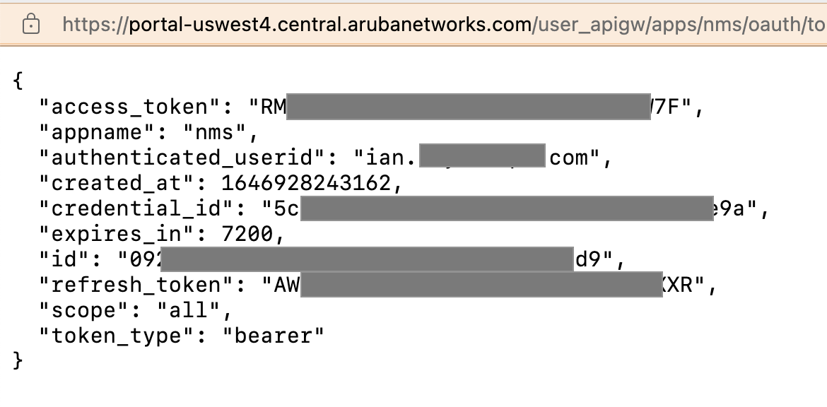
Note: once you’ve generated your token, make sure you download it by clicking “Download Token”. It will open a new window containing the JSON text with the actual token in it. Save this to a text file which you can use with your scripts later. Note the expiration time on this: 7200 seconds. This token isonly good for two hours. You will need to use the refresh token in there to keep it alive past the 2 hour window. The refresh token is good for 15 days. How? It’s in the docs listed above (yeah, I just dropped an RTFM on you!)
Programming with the API
(and a gratuitous plug for the Aruba Developer Hub)
If you want to access the API programmatically, you’ll want to use Python, although anything capable of making HTTP calls and processing JSON responses will work. Fortunately, Aruba has provided a Python library (again, on the Aruba Developer Hub – this site has a wealth of great stuff).
The documentation on how to install the Python libraries can be found on the Developer Hub. At some point, you’ll likely be referred to the documentation for the library on Read The Docs. This documentation is broadly good, but in some places omits a few key points. Most notably, any time you need to send data to the API in a POST call, it’s not immediately apparent that body data needs to go into the apiData parameter.
Plenty of examples on the Dev Hub, and what you do will depend on your workflow and what you’re trying to accomplish. It may be helpful to draw yourself a mind map of what steps are needed to perform a task, and then map out what API calls and Python classes are required to make them, as well as what input data it depends on. Practice good code hygiene and don’t ever put your tokens in your code lest you accidentally share it to the world when you share your code (this is partly why the tokens on Aruba Central are only good for 2 hours!). Instead refer to the token file I suggested you download earlier (which you can do simply by opening the file and doing a json.load to import the contents into a dict.)
It’s also worth noting that the Aruba Central API does not provide you with any access to the Aruba Activate provisioning system (this is a bit of an annoyance to me, but out of my control). This has recently been given a major overhaul and has been migrated to the HPE GreenLake Platform and is now under the GreenLake device management function. There is an API for many GreenLake functions (see also: the HPE Developer Hub), but from what I understand, the platform is presently still migrating the API. I’ll update the post as soon as it’s available. (and did you know that if you have HPE servers, the ILO management subsystem also has a REST API? API ALL THE THINGS!)
If you’ve been using Ekahau for a while, you probably already know how painful it can be to generate a list of APs from within a custom report template – and even then, it’s not the most useful thing in the world just for being in Word format.
One of the most underrated features of Aruba wireless hardware is its ability to be used as a wireless bridge. Running a cable to provide power and data to an AP is always the best way, but sometimes you just can’t get one there and have to go wirelessly.
With the release of Instant v 8.4, the concept of a mesh cluster name and key was introduced along with the AP-387 5/60GHz outdoor bridge. This mesh cluster mode lets the APs in the cluster establish their own mesh SSID and encryption, without the brain damage of provisioning those parameters on each device. This also introduced the concept of a standalone Instant AP, which allows you to run a point-to-point bridge or a multipoint mesh without the AP trying to join an existing Instant Virtual Cluster (VC).
Once a bridge is established, it is fully transparent at L2. Anything that shows up on the interface on the Mesh Portal AP will pop out the other side on the Mesh Point’s bridged Ethernet interface. You can optionally prune VLANs if you need to.
Key Terms:
WIRELESS MESH : one or more access points that connect to the network wirelessly.
MESH PORTAL/MESH ROOT: an access point in a mesh network that is connected to the network via an Ethernet connection. An Aruba AP configured for mesh will determine if it is a portal by listening for traffic on the Ethernet port. a given mesh cluster can have multiple portals.
MESH POINT: an access point in a mesh network that is connected to the network via one or more wireless connections to a Mesh Portal. Mesh points can also provide a wireless connection to another mesh point, but you don’t want to go more than one or two hops to a root bridge. If you have to go long distances, a linear mesh topology may be more useful. An Aruba AP will determine it is a mesh point in a cluster by either not seeing traffic on the Ethernet ports, or if the Ethernet port is set to bridging mode and has devices downstream.
MESH CLUSTER: A group of Aruba APs that are configured for the same mesh.
What you will need:
two Aruba APs that support Instant 8.4 or higher. Update them to the latest 8.10 or 8.7 LTS code trains if you can. I labbed this up on a pair of AP-515s, but the APs don’t necessarily have to be the same model of hardware, just the same software version. The Aruba mesh will operate on 5GHz.
A means of powering both APs. This can be PoE, but you’ll want the network on the Mesh Point side of the link to be an isolated Layer 2 segment from the one on the Mesh Portal, otherwise you’ll create a loop when the bridge comes up. It’s generally easiest to put a separate PoE switch on each end, making it easier to connect devices to troubleshoot. If using PoE, make sure it’s sufficient to run the AP.
Not strictly necessary, but helpful: A console cable for each AP. The 570 series APs use a standard USB Type C connection and ship with the requisite cable. Otherwise you’ll need either the “Orange Cable” (JY728A AP-CBL-SERU) that has a Micro-B connector on the end (this isn’t actually USB, so don’t even bother trying to use a standard MicroUSB cable), or the older TTL pin header to DB9 cable.
To start, hook up the console cable to the AP, and power it on. When prompted, stop the boot loader. Once at the boot loader prompt, issue the following commands:
sets the AP to standalone mode (ignores any incoming L2 Instant VC broadcasts and suppresses any outgoing ones)
Sets the AP to Controllerless (Instant)
Saves the environment variables
Boots the AP.
You can also do this from a booted AP on the AOS CLI by issuing the following commands:
write erase all
swarm-mode standalone
reload
Once the AP is booted up into standalone mode, you’ll need to log in via the GUI or the CLI (console or ssh) using the default credentials (admin/admin or admin/serial#), and set a new admin password. Once you’ve done this, you’ll need to create an access SSID to get it out of Instant’s SetMeUp mode. You can disable this later if the AP is not also being used for access (generally not a good idea on a mesh bridge, unless you’re restricting it to the 2.4GHz radio which is unused by the mesh.) If you’re using an AP-387, you don’t need to do this.
Once you’ve created this dummy/temporary SSID (easiest from the Web UI), go to Configuration>System>Show Advanced Settings, disable Extended SSID and reboot.
On the CLI:
conf t
virtual-controller-country US
name Mesh-Portal (or name of your choice)
no extended-ssid
exit
commit apply
reload
virtual-controller-country is vital here. The AP will not do anything on RF until this is set.
Once the AP is back up, configure the mesh:
no mesh-disable
mesh-cluster-name <cluster name> (If doing multiple bridge links, each one must have a unique name)
mesh-cluster-key <cluster-key>
commit apply
If you’re in a multi-VLAN environment, this is also a good time to set VLANs and such. If you’re just running a flat network, skip this part.
uplink-vlan <VLAN ID> (this is the VLAN the AP listens on)

#If configuring a static IP:
ip-address <ip-address> <subnet-mask> <nexthop-ip-address> <dns-ip-address> <domain-name>

conf t
wired-port-profile Mesh_Portal_Uplink-wpp
 switchport-mode trunk
 allowed-vlan <list of VLANs or "all">
 native-vlan <port Native VLAN>
 trusted
 no shutdown
 type employee
 auth-server InternalServer
 captive-portal disable
 no dot1x
exit

enet0-port-profile Mesh_Portal_Uplink-wpp
enet1-port-profile Mesh_Portal_Uplink-wpp

exit
commit apply
Check the status of the mesh cluster settings with:
show ap mesh cluster status
It should look something like this:
Mesh cluster      :Enabled
Mesh cluster name :Mesh_Lab
Mesh role         :Mesh Portal
Mesh Split5G Band Range :full
Mesh mobility     :Disabled
Now you’ll want to do the same process on the Mesh Point AP, plus the following to enable the bridging (you can also do this in the boot loader by doing setenv enet0_bridging 1 and savenv):
enet0-bridging
commit apply
reload
Once everything is booted back up, give it a few minutes to establish the mesh link, and then run:
show ap mesh link
Which will give you information about the link. the RSSI column is the SNR in dB. You can see from the flags that the link is running an 802.11ax/HE PHY (E), that legacy PHYs are allowed (L), and that it is connected to the mesh portal (K).
# show ap mesh link

Neighbor list
-------------
Radio  MAC                AP Name          Portal  Channel  Age  Hops  Cost  Relation                 Flags  RSSI  Rate Tx/Rx  A-Req  A-Resp  A-Fail  HT-Details    Cluster ID
-----  ---                -------          ------  -------  ---  ----  ----  -----------------        -----  ----  ----------  -----  ------  ------  ----------    ----------
0      aa:bb:cc:dd:ee:ff  Mesh_Lab_Portal  Yes     116E     0    0     4.00  P 22h:18m:57s            ELK    55    1531/1701   1      1       0       HE-80MHz-4ss  29c8af3dec64e7c278bfcbfab07a2a3

Total count: 1, Children: 0
Relation: P = Parent; C = Child; N = Neighbor; B = Blacklisted-neighbor
Flags: R = Recovery-mode; S = Sub-threshold link; D = Reselection backoff; F = Auth-failure; H = High Throughput; V = Very High Throughput, E= High efficient, L = Legacy allowed
        K = Connected; U = Upgrading; G = Descendant-upgrading; Z = Config pending; Y = Assoc-resp/Auth pending
        a = SAE Accepted; b = SAE Blacklisted-neighbour; e = SAE Enabled; u = portal-unreachable; o = opensystem
From this point, you should be able to send traffic across the link, and you’re ready to go install the bridge in its permanent home. If running outdoors, don’t forget to ensure a clear line of sight and unobstructed Fresnel Zone.
Another quick bit today – this is the basic framework for using the REST API in ArubaOS. Lots of info at the Aruba Developer Hub. This is primarily for executing show commands and getting the data back in a structured JSON format.
However, be aware that not all show commands return structured JSON – some will return something vaguely XMLish, and some will return the regular text output inside a JSON wrapper (originally the showcommand API endpoint was just a wrapper for the actual commands and would just return the CLI output, as it still does for several commands)
You can always go to https://<controller IP>:4343/api (after logging in) and get a Swagger doc for all the available API calls – although owing to system limitations, the description of those endpoints isn’t generally there, but it can be found in the full AOS8 API reference.
This blog entry does not deal with sending data to the ArubaOS device.
Just a quick post today to highlight a couple of my favorite ArubaOS v8 CLI commands of the week.
The first is show configuration diff <node A> <node B>. This handy tool lets you compare what’s different between two different hierarchy containers. Great for chasing down obscure config items.
The second is show references, followed by a profile type and name – it will tell you all the profiles that reference the one provided. Very handy if you’re trying to clean up cruft and want to find profiles that are abandoned and no longer useful, or if it won’t let you delete a profile because it is still in use (where it will annoyingly not actually tell you where)
It’s not uncommon for architects and interior designers to get on us wireless guys for cluttering up their aesthetic, so I always try to get on their good side whenever possible. They don’t tend to complain about “necessary” stuff like light switches and fire alarms, but for some reason, they never see network infrastructure as “necessary”.
Near The Floor. Sometimes, the wall finish is such that using adhesives or screws is practically a capital offense. It could be fabric, glass, metal, or whatever. At that point, you’ll usually have a baseboard upon which to mount them, just make sure it’s not going to get damaged by floor cleaning processes. Another reason to go close to the floor is to use the floor to create a shadow when deploying near an open hole like an atrium or a stairwell. You don’t generally want your beacons from one floor being visible on another, as that can really confuse a map that is not aware of floor holes. It’s also important to always place a beacon near every “portal” at each floor (doors from stairwells, elevator lobbies, and so forth) so the app knows when you’ve changed floors and to switch maps when navigating.
On The Wall. I’ll explain in a minute why you want your beacons as close to the user as possible. What this generally means is that you want to go on the wall most of the time. In terms of spacing, you should generally be within 3-4m of a beacon anywhere in the building. Being closer to your beacons will improve accuracy, and greater beacon density will reduce latency (but only to a point, it typically takes 2-5 seconds for the app to get a new fix because it has to listen for all the beacons it can hear) .
On The Ceiling. Suboptimal, but works in a pinch. Suboptimal mainly because even standing directly under the beacon, you’re usually at least 2m away from it.
Now for the engineering reasons behind all this: It all comes back to the old friend that wireless engineers everywhere love and cherish: free space path loss. Except here, we’re making constructive use of it.
Determining distance based on triangulation of beacon RSSI is optimal within about 0-4 metres due to the inverse square law of RF propagation. Typically, the calibrated output of the beacons is 0dBm (1mW). They operate in the 2.4GHz band on a 2MHz advertisement channel tucked between Wi-Fi channels 1 and 6, as well as one just past channel 11, and another one just below channel 1. My colleague Joel Crane explained BLE frequencies in 60 seconds (when he was at Mist, now he’s at Hamina after a brief stint back at Metageek)
There’s also some variability between receiver devices in terms of their sensitivity and even based on internal antenna configuration and how the device is held/oriented, so let’s just assume it’s +/- 3dB for the purposes of this example because it makes the math simpler.
Free Space Path Loss, Illustrated by my good friend and colleague François at Semfio Networks
When the receiving device sees a BLE beacon, it then determines its distance from that beacon based on the RSSI (and uses the beacon’s ID to correlate it with the device’s placement on the map). When it sees a beacon at -35dBm, it knows it’s under a metre away. If it sees it at -55dBm, that could be anywhere between 4 and 8 metres away. So the farther you get from the beacon, the wider that margin of error becomes. Any walls that get between can also add 3dB or more of attenuation depending on the materials used. (just like they do with Wi-Fi, since we’re dealing with the same RF frequencies, just at about 1/1000 the power).
Below 1 metre, every time you halve the distance you gain 6dB – so 50cm would be -34dB, 25cm would be -28dB, 12.5cm would be -22dB, and now we’re getting really close to the beacon, and it’s already lost 99% of the transmitted power… Also worth noting here that when you mount them on a metal surface, you gain a little bit back, but if your surface is less than one wavelength (~12cm) wide, the math gets tricky and I won’t go into it here.
What this means for placement is that you want to get them as close to the receiver as possible, usually within 4m. This generally means at a height of 1-2m on walls, and between 40 and 55 inches is ideal, since it avoids hips, shoulders, and carts which could damage the beacon or outright rip it off the wall (and collisions with a hip or shoulder is not fun for the owner of the hips and shoulders either… ask me how I know). They can also be placed on ceilings, but as I pointed out previously, in an office building, that usually means you’re never going to get closer than ~2m to the beacon even if you’re standing directly underneath it. Beacons near the floor are about a meter closer to the receiving device than the ceiling would.
In a recent deployment, the basic beacon grid (best practice: 10m) was deployed on the structural column wraps, which were spaced about 12m apart. The gaps in the middle of the squares formed by 4 columns were filled in with AP based beacons (which isn’t always dead center due to some variability in the AP placement within those squares). In the common central areas on each floor, we had to fill some of those gaps with additional beacons to get within about 4-5m and provide greater accuracy due to the various obstructions, as well as place beacons near the areas where traffic enters and exits those spaces.
In locations where there are particular aesthetic concerns, it is usually possible to paint the beacons and their mounts to match, as long as the paint does not contain any metallic materials (lead, aluminum powder, gold leaf, iron oxide, etc.), or you can apply a vinyl skin. This also applies to access points. Check with your vendor to make sure it will not void the warranty (as it tends to do with many vendors). You can also often find snap-on paintable covers for indoor APs if you don’t want to paint them directly.
Applying this to design methodologies
So how do you plan out a beacon deployment? Same way you generally would with any RF planning. Ekahau supports modeling BLE access points (although it cannot survey them, much to my annoyance). At this point you want to set your BLE coverage requirements to the RSSI required for the most distance you want to be from the beacon, which is -52dBm, and you want to make sure that within that coverage level, you can always hear at least 3 beacons.
How it works with clients
(added July 2022)
How Bluetooth beacons work with clients is the subject of a lot of confusion on the part of the end users, especially those who are concerned about tracking, especially with the rise of Apple’s AirTags (more on those in a minute) and other personal item trackers.
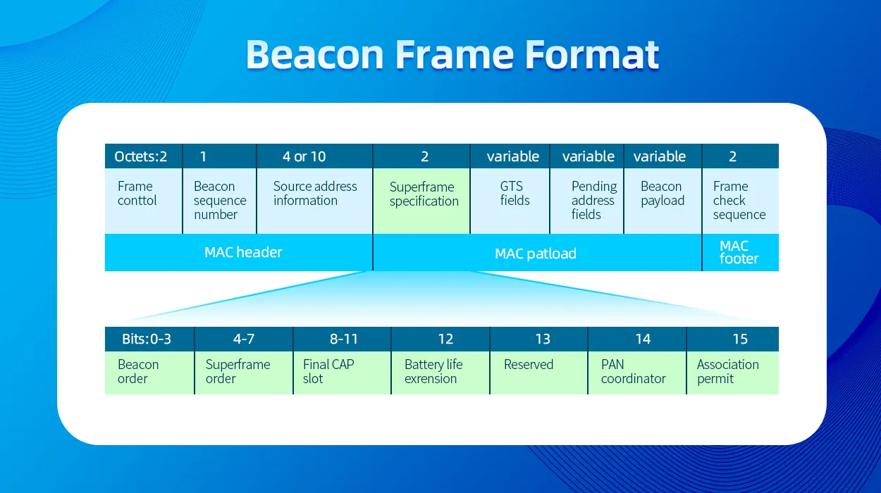
The good news is that a BLE beacon is nothing more than a small circuit that blips out a small identifier at regular intervals (Aruba beacons do so every second). It has no idea where either it or you are. Generally speaking, the payload of the beacon is very small, consisting of a major ID and a minor ID. Other ancillary data can go in there as well.
BLE Beacon Frame Format (source: Mokoblue.com)
The Major ID generally identifies the beacon type, and the Minor ID identifies the individual beacon. If you open up a BLE sniffer, you’re surrounded by beacons almost everywhere you go. Your smartphone sees all of them, but if it had to look up what every single one does, it would nuke your battery in very short order. So what happens is that when you install an application that makes use of beacons, it tells the OS (IOS or Android or whatever) that it wants to know about any beacons with a certain Major ID. The OS then asks the user if they want to allow the app to receive data about nearby network devices (IOS, I don’t know offhand how Android does it).
Once the app has permission, any time the OS sees a Major ID that has been registered by an app, it will send that beacon info to the app, which then processes the data. Apps like Meridian that do location then have information from the back end that tells it where each beacon is located, and from that, based on the signal strength of the beacon, it can multilaterate the user’s location. Waze uses this approach to provide additional location in satellite-weak areas like tunnels. But anyone with an app that knows what to do with a particular beacon can benefit from it.
Which brings me to how Apple AirTags work. Apple has done a really good job of creating an asset tracking solution that ensures the tag owner’s privacy. An AirTag is still just a BLE beacon (with some extra stuff), and the Find My app has registered the Major IDs with the OS (from the factory – and it doesn’t have any special access to the OS). Where AirTag got really clever, is the Minor ID/payload is the owner’s public key (which is unique to that specific tag). This keypair is generated when the tag is activated If it’s detected by someone other than the owner, that device takes its location (from whatever source the OS location services has), the signal strength, and the time, and encrypts that using the public key, and uploads it to Apple’s servers. Only the owner of the tag who has the private half of that key pair (stored in the device’s TPM) can decrypt the payload. And if a particular device sees someone else’s tag with a constant signal strength as the device moves around, after a while (an hour or two) it will determine that someone may be using a tag to track you and warns you. A few months ago, my daughter went on a school band trip and borrowed my suitcase, which still had an AirTag buried in it from a recent trip to Europe. About halfway across Iowa, almost 100 kids in three separate buses (including my daughter) simultaneously got an alert on their iPhones that an AirTag might be following them. They all found this incredibly amusing.
Tile’s product works in a very similar manner, but I don’t know if it does the encryption thing (which is likely patented by Apple). Apple’s product benefits from a much broader client detection base due to Find My being installed on every iPhone, so anyone with an iPhone can see and handle an AirTag. Handling a Tile beacon requires the Tile app to be installed (and some bluetooth devices like headphones are able to be located with Tile), which limits the reach. As far as I know, there’s nothing that would prevent Tile from adopting the Find My device spec. There have also been some Proof-of-Concept deployments where BLE-capable infrastructure such as Aruba Wi-Fi can also report these types of beacons back to their respective service providers.
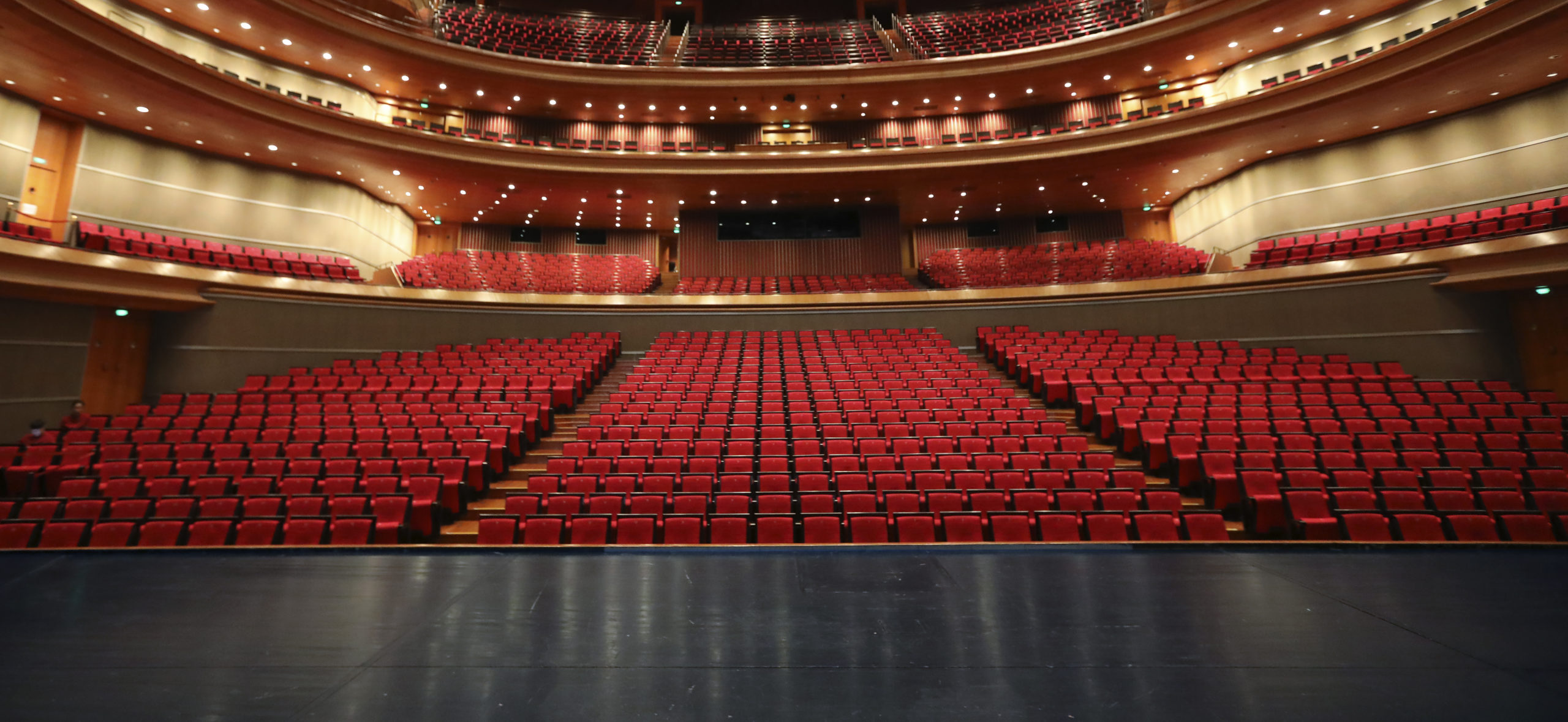
I was recently (March 2021) tasked to do a design for a small 450-seat auditorium and provide capacity and throughput numbers. Those who have known me for a while probably know that this type of auditorium is kind of a sweet spot for me, having done designs for a number of church sanctuaries of various sizes. In this post, I’m going to get into the nitty gritty details of making sure that not only does an auditorium have sufficient wireless capacity to meet the connectivity needs of the space, but also to have realistic expectations of what the performance will look like in order to build sufficient backend networking infrastructure without needlessly overbuilding it.
Auditorium design should be simple, right? Here’s how I have seen it done, way too many times to count:
Count up how many seats there are, divide by some number of seats per AP (usually based on the AP data sheet), and then figure out how many APs that gets you.
Figure out your capacity by taking the AP throughput (again from the data sheet) and multiplying that by the number of APs. Then divide that capacity so you know how much bandwidth you get per person.
Try to do a predictive model using Ekahau, to place the APs in exactly the right spot, and without ever surveying the space.
So let’s say you have a 1000-seat sanctuary where you want to use a Ubiquiti Unifi HD access point because that’s what your colleagues on social media recommended. The vendor data sheet says that you can do 500 concurrent clients per AP, so that means two APs (let’s say three just for redundancy), and each AP can do 2533 Mbps . So you should be able to get 7.6 Gbps, divided by a thousand seats, which gives you 7.6 Mbps per client, and you’ll need a 10 Gbps switch. Easy job, under a thousand bucks for the gear. And then when you fill the room up, the whole thing collapses, everyone is complaining about how it doesn’t work, and you’re left wondering why.
Because that’s not how any of this works.
For starters, never believe the data sheet. That’s marketing, not engineering. There is no amount of marketing copy that can ever overcome the fundamental laws of physics. So let’s pick this design apart, piece by piece… (yes, I’m gonna pick on Ubiquiti for a bit here, because their UniFi brand is often thrown about as a solution to all your wireless problems by people who don’t actually understand how wifi works – but these principles apply to any vendor – no vendor has a magic bullet, you still have to do the engineering)
Caution: Math (or at least some basic arithmetic and some elementary statistics) ahead. Don’t say I didn’t warn you. Hope you paid attention in school. (If you’re still in school, pay attention: you will use this stuff in real life!)
The Engineering
Winging it: Ur doin it rong.
Error #1: AP Throughput
This is probably one of the most egregious attempts by the marketing department to ignore reality. This number published on the data sheet (and also frequently wielded by consumer AP marketing) is completely bogus, but marketing loves to show off big numbers. It is typically created by taking the maximum possibly PHY rate (more on that in a second) on each radio, and adding them together. (why? you can’t aggregate client radios like that!). The number “2533 Mbps” comes from adding the max PHY on 5GHz (1733 Mbps) with the max PHY on 2.4 GHz (800 Mbps)
What is the PHY rate?
It is the speed at which an individual wireless frame is transmitted over the air. It can vary from one frame to the next, one client to the next, and is highly dependent on RF conditions. What goes into the PHY:
Channel Width
Number of MIMO Spatial Streams
Guard Interval
Modulation and Coding Scheme (MCS)
Resource Unit Size (in 802.11ax)
A table of all possible PHY rates (and the math behind them) can be found at the ever-handy mcsindex.com.
And here’s where this speed number comes flying apart. In order to achieve this maximum PHY, you need to use an 80 MHz channel (40MHz on 2.4 GHz, which is a monumentally bad idea), a short guard interval, 256QAM with 5/6 coding (which typically requires signal:noise ratio of over 40dB to achieve), and FOUR spatial streams. Given that the vast majority of devices in the wild only support two spatial streams (and the only 4SS client device is a desktop card), it’s safe to say that you’re never going to even come close to that maximum PHY rate. And even then, wireless is a half-duplex shared medium where only one device can talk on a channel at a given time. So even if you were to somehow get that max PHY, your throughput for a single device might be about half that at best. And as you add more clients, it gets even lower. Remember: Every TCP segment results in FOUR transmissions on the wireless: The segment itself, the layer 2 acknowledgement of that frame, then the TCP acknowledgement, and then the layer 2 ACK of the Layer 3 ACK.
To illustrate this, I will refer you to Aruba’s throughput test of the new AP-635, an access point that supports the 6GHz band. If marketing were to tell you the throughput of this AP, it would sound something like “3.9 Gbps” (and, in fact, the data sheet will tell you exactly that, as this is a 2×2:2 access point). But in the real world, running the widest channels on all bands, actual throughput was a bit over 2.3Gbps, and 2/3 of that was on 6GHz… Still impressive, but it also shows why you don’t actually need a 10Gbps link to it.
Error #2: Constrained Resources
The most important thing to remember when doing dense Wi-Fi deployments is that your most constrained resource is not bandwidth, it’s airtime (the amount of time a given device gets to send data). In order to maximize airtime sharing, you want devices to get on, say their piece as fast as possible, and get off. This also means you want them to use as little spectrum as possible to do so. The key to supporting more client devices is to minimize their use of spectrum and maximize spectrum reuse (where multiple access points use the same frequency in a way that they don’t interfere with each other, which is a lot harder than it sounds)
Ultimately, the only way you can add capacity to a space is to add spectrum. I’ll demonstrate in a minute how channel width matters a lot less than one might expect.
And let’s not forget that while this AP advertises throughput of 2533Mbps, it only has a 1Gbps port to connect to the switch…
Error #3: Assumptions
We’ve probably all heard the old saw about what happens when you assume something. It still holds true in wireless engineering. An auditorium may have a thousand seats, but it’s also vitally important to understand how that space is used, what kinds of devices there are, how many people, etc. Broadly speaking, an auditorium will “feel” packed and completely full when there are about two thirds of the seats occupied. But if you’re selling reserved tickets, it’s entirely possible to fill every one of those seats. And what devices are those people bringing? There’s a big difference between a 1000-seat auditorium that has 700 people in it for weekly worship and when that same space has 500 people in it attending a conference, or when 1000 people are there watching a film or a performance. Ultimately you want to plan around the most likely intensive usage scenario, which is going to typically be a conference (although I’ve done plans that assume the most intensive scenario is something completely insane like an Apple product launch).
Planning (Doing it right)
So let’s run the numbers for this fictitious auditorium that seats a thousand people. broadly speaking, this room is going to be of such a size that no matter where you place the AP, it’s going to light up the whole room. At this size, you’re not going to get any frequency reuse, even with directional antennas. If you were hoping to use the crowd to attenuate the signals and get reuse that way while putting your access points under the seats, stop now – Aruba (who have tested and deployed a whole lot of venues of all sizes) do not recommend going under the seat in any venues under about 10,000 seats unless you simply don’t have a means to go overhead.
Since we’re not getting any channel reuse, this gives us a grand total of 500 MHz of spectrum to work with, plus another 60 MHz in the 2.4GHz band – but it’s probably best to simply forget about 2.4 GHz in an auditorium because a bunch of A/V stuff is using it (and likely ill behaved stuff at that), not to mention the hundreds of wearables the people in the seats have, which will light up the entire Bluetooth channel space. So let’s go with 5 GHz for now. I’ll talk about 6GHz later.
I’m gonna go ahead and say it: Don’t waste your time with 160MHz. Sure, you get some sick PHY rates with it, but device support is limited. And don’t forget that weather radar can remove 3 channels at 20 MHz, 2 channels at 40 MHz, and 1 channel at both 80 and 160 MHz – but unless you’re very near a radar site, and the radar is penetrating from outside, you can use these channels without any issue. I’ve even seen these used inside airport terminals within view of the TDWR. Use these channels right up until you can’t.
So how do you choose what channel width to use? The only difference is whether you have more devices talking at once, at lower speeds, or fewer talking at once, but doing so at higher speeds. In the end, it doesn’t make that much of a difference to your throughput, and then it becomes a decision of how many APs you can physically put in the space (and their specific placement in a small auditorium is not too picky, since every AP lights up the entire space). 12 APs is a good flexible middle ground here, because you can do 12x40MHz channels. or 24x20MHz if the AP supports dual 5GHz radios (such as the Aruba AP-340 or AP-550 series access points), or 6x80MHz and leave the other 6 as spectrum monitors. Or adapt as needed.
Let’s now plan on a full conference load of 500 people, who each brought a laptop, a smartphone, and a tablet. and will be evenly distributed throughout the room (because elbow room and personal space). The tablet and the phone will be doing typical low-usage background stuff while the laptop will be doing much heavier usage, let’s say 1 gigabyte per hour (which is roughly equivalent to a 2Mbps video stream – I’m thinking this is something like the Church IT Network conference or the Wireless LAN Pros Conference and they’re all geeks doing geek stuff during the conference, and that about 3/4 of them are active, the rest have shut their devices off to minimize distraction. I’m also going to plan on these being 2SS MIMO devices, since that’s the overwhelming majority of what’s out there.
So here’s the breakdown, assuming most clients link up at MCS7 with a standard Gaussian distribution on either side. We’re also assuming a 50% net ratio of usable throughput (goodput) to PHY speed. Duty cycle is how much of the available airtime is used for this load – you want to try and stay under about 60% to accommodate for neighbor interference, etc. Much above that and performance really starts to suffer. These calculations are based on an Excel sheet that I have, but it’s a little rough around the edges, so I haven’t shared it here. Hit me up and I can send it to you.
24x20MHz
12x40MHz
6x80MHz
Devices
1130
1130
1130
GB/Hour
400
400
400
Available Throughput
1560
1620
1755
Duty Cycle
57%
55%
50%
Average Throughput per client
1.38 Mbps
1.43 Mbps
1.55 Mbps
And this is where things get a bit counterintuitive (as they often do with Wi-Fi): You’re slightly better off here going with fewer APs at 80 MHz than you are with more APs at 20 MHz – but if you lose an AP or a channel due to failure or radar hit, you lose a lot more capacity when using the wider channels. In any case, you can see that all you actually need for this room is a gigabit switch with a 10G uplink, and a decently fat pipe to the internet. You also need at least a /21 IP address space (but probably a good idea to go to /20 or even /19 to accommodate for MAC randomization). You also want to plan on sufficient AP capacity outside the space for devices to transition to during breaks and whatnot, but they won’t need nearly as much airtime capacity as those devices are not going to be using it as heavily as the laptops.
The Math (I warned you!)
Input data:
Infrastructure:
Area Population (Head Count) – the number of people in the room.
Distribution Curve: Normal/Gaussian
Number of access points (self-explanatory)
Channel Width (2.4GHz, 5 GHz) (Not directly used in calculations, only in determining link speed input)
Client Devices:
Wifi Devices per person (Distribution: triangular)
Gross Take Rate/how many people using wifi (Distribution: Gaussian)
% Devices on 5GHz (if using both bands)
Client Activity Modes: (activity per hour, in MB)
High/Medium/Low (Gaussian)
Activity Distribution (percentage of traffic in each mode, Gaussian)
Link Parameters (I shoot for the MCS7 values on 2SS – but what you can realistically expect will also be a function of how far the AP is from the seats, which is a factor in tall rooms):
2.4 GHz Link Speed (Mbps, median speed, triangular)
5 GHz Link Speed (Mbps, median speed, triangular)
TCP Net ratio (Goodput/Link speed, triangular)
Distribution Curves: a) Normal/Gaussian, b)Rectangular/Uniform, c) Triangular/Continuous, d) U-shaped/quadratic
Output Data:
Connected Devices: Headcount * Devices per person * Take Rate
Available Throughput (Mb/sec): AP count * Link Speed * Goodput Ratio
Duty Cycle: ((Client Demand * 8)/3600) / Available Throughput
You’ll also want to apply the distribution curves to all those values to establish your 95% confidence ranges. Hit me up if you want details..
You can also improve your airtime efficiency by narrowing the range of PHY speeds so as to keep extra slow clients from connecting and chewing up your airtime – This is accomplished by setting your basic and available data rates to a higher value such as 12 Mbps or 24 Mbps. Also, don’t forget that because any slice of airtime is at a premium, don’t go crazy with your SSIDs, to keep your beacon overhead under control even at the higher basic rates. You also don’t want to “hide” any SSIDs in order to keep your unassociated clients from chewing up airtime with probe requests that are trying to figure out if the hidden SSID is one they know about. You want as many devices in the room as you can get to associate to something, anything and shut up with the probes already. Even if it’s an open SSID that goes nowhere.
Caveats
It is worth noting here that artificially throttling client speeds will do more harm than good – the additional traffic overhead that comes with that eats up airtime like crazy. So don’t see this and think you should limit your client devices to 2Mbps in order to make sure the system doesn’t get overwhelmed – see Jim Palmer’s presentation “The Netflix Effect on Guest Wi-Fi” for why throttling client speeds doesn’t work the way you think it does. Then show it to your boss to dissuade them from insisting on meddling in the affairs of dragons.
These calculations also don’t factor in any airtime overhead from adjacent APs outside the space, which is one reason why you want to keep your airtime duty cycle under 60% and your goodput ratio to 50%. Once the system is deployed, you’ll want to validate in the field what they actually look like, which will give you a good idea of actual usage and how well the model predicted your capacity.
And, of course, all this assumes that your client devices are going to be bashing away at the network constantly, which is a fairly unusual occurrence. But you’re planning for the worst case, right? If actual usage is lower, then each client will get more throughput.
What about placement and directional antennas?
In an auditorium this size (or any size, unless it’s an arena or a stadium, that seats thousands), it really doesn’t matter. Because no matter where the AP is or what antenna it has on it, it will light up the entire room, even at a low power setting like 10dBm. Don’t get me wrong, I’m a huge fan of using directional antennas to sculpt the RF footprint. But unless you’re dealing with a small stadium, you’re not going to get frequency reuse out of directional antennas anyway (and a directional antenna can actually cause you more trouble – if the hot spot of the signal is too narrow, even way off-axis you’ll still be above the -82dBm contention backoff threshold in most of the room due to reflections and how focused your antenna is). If you want a good visual of this, go find one of the lighting people and ask them to aim a lighting fixture with a narrow beam at a seating area, turn on only that light, and vary the brightness… You’ll get enough scattered light in most of the room to see where you’re going. Light is, after all, still electromagnetic energy, so your RF is going to behave in similar ways.
Because the APs light up the whole room, you can literally put them anywhere that’s convenient for installation or maintenance access (just don’t put them too close to each other). There are however some cases where you can (and probably should) use a directional antenna in an auditorium space:
Tall ceilings – if you’re stuck with mounting the APs on a ceiling that’s much more than about 10m from the seating area, use a directional – at that height, 90° is still going to cover the entire floor, and 60° likely will too (remember that antenna beam width is considered to be between the -3dB points on the antenna plot, and in a space like an auditorium, your functional beam width is going to be closer to between the -10dB points, and you’re going to get a lot of scatter from the back lobes of the antenna as well, something that Ekahau doesn’t model – but this multipath environment can ultimately help with MIMO.
Keeping the signal inside and the noise outside – this is another place where you might consider directional antennas – if your APs are near the perimeter of the space and there’s space outside that also has Wi-Fi, a directional antenna can keep the outside signals from causing contention, as well as keep the signal from spilling into the area outside and causing contention with the APs external to the room. It’s also probably a good idea when you’re building a new auditorium to build the shell of the room such that it has high attenuation between the outside and inside (tilt-up precast concrete panels are great for this, but there’s a case to be made for intentionally designing RF shielding into the walls. It probably doesn’t hurt to set the room to a different BSS color if you’re using 802.11ax – but I haven’t yet encountered this in the wild. Last year, I was working from someone else’s design in a cruise ship where there were no fewer than 40 APs in the ship’s theatre, which seated 750. These APs were not only using a 60° directional antenna, it was placed immediately behind an expanded metal mesh used to support acoustic treatment fabric. And yet even at the lowest power I thought I could get away with, that one AP was still lighting up the seats below (about 6m away) at -60dBm… The back lobe of these antennas was bouncing off the steel structure of the ship, and the weakest spot in the room was directly on the center axis of the directional antenna. I ended up putting most of those APs in spectrum monitoring mode, and making notes for the next ship auditorium. Upside is that a steel ship gets GREAT frequency reuse elsewhere.
Aesthetics – Sometimes you just want to hide the APs – and in that situation, an external antenna can be easier to hide than a whole AP.
Note: most APs now also have BLE functionality, and because of the power levels involved, the BLE antennas are still inside the APs even if the Wi-Fi antennas are external. So if BLE is a design consideration, keep that in mind.
You can also hide APs (or antennas) by skinning them (printable automotive vinyl wrap is great for this), painting them (if the manufacturer allows this, just make sure you use nonmetallic paint), a paintable cover (Aruba offers matching paintable covers for almost all of its indoor APs) – I haven’t tried it, but I wouldn’t be surprised if you could also hydro-dip the covers or the radomes. You can also hide APs in an enclosure such as the Oberon 1019-RM or otherwise camouflage them (See previous post: Hiding In Plain Sight). But one thing you don’t want to do is put them all being the acoustic panels where they all have line of sight to each other, as this will screw with 802.11k as well as automatic channel/power algorithms like AirMatch. This is functionally the same as putting your APs above the ceiling tiles.
Too Much of a Good Thing?
If you’re dealing with a larger space where an AP doesn’t cover the entire space, check your predictive model or your survey for the number of APs visible on the band at any given location – if that number exceeds the available spectrum divided by your channel width, then you’ve got too many APs in the space (conversely, you can plan your AP coverage such that you never exceed that number (for example, 12 APs if you’re using 40MHz channels on 5GHz), you’ll maximize your spectrum reuse. You can always double up if you’re big on redundancy, but you’re not going to get any additional throughput or airtime out of it, and there are better ways to do that.
What about 802.11ax?
802.11ax (“WiFi 6”) brings a few airtime efficiencies to the table, but that will mostly manifest itself with the low traffic clients that don’t need to use the full data payload of a frame. High traffic clients will typically use all the RUs available in a single transmission, so our airtime usage calculations should not assume any OFDMA gains. BSS coloring (see above) may also be useful.
What about MU-MIMO?
Even if you have devices that support it (rare in 802.11ac, required for 802.11ax), MU-MIMO frames don’t really happen all that often in the real world, so planning your capacity around being able to use it is not a great idea. If you can somehow get MU-MIMO, then you’ll see some more efficient airtime usage. Again, we can’t count on this, so our capacity calculations should assume it isn’t happening. Once deployed, monitoring is important to see how the throughput and MU-MIMO usage actually behaves in your environment and so you can refine your calculations and models.
What about 6 GHz?
6 GHz is pretty simple – you get to add more lots more spectrum (about 3x what 5GHz offers), which directly translates to more capacity/throughput. Vendors have begun releasing tri-radio/tri-band access points (Such as the Aruba AP-630 and AP-650 series) that add the ability to run a 6 GHz radio, so you would simply calculate the additional capacity as additional APs and swap them out when the APs become available.
But also consider that client support may not be fully available for a few years, so when you run your calculations, do them for 5GHz only and then treat 6GHz as a supplemental capability. If you’re running a dozen 5 GHz APs with 40 MHz channels, you can use those same 12 APs with 80 MHz channels on 6 GHz and the higher throughput alone should encourage any 6 GHz capable client device to choose the 6 GHz connection. Band steering without the band steering.
Leave it. Pretend it doesn’t exist. An auditorium full of people is going to be chock full of Bluetooth signals from wearables and wireless earphones (not to mention an increasing number of hearing aids). There’s also a lot of A/V stuff that lives in 2.4 that you just don’t want to worry about either. If you’re unable to convince the theatrical engineers to integrate with your existing infrastructure, you may also want to leave one 20MHz channel on 5GHz for them (165 is easy). And you only gain 60 MHz of spectrum, at the expense of a lot of headache.
tl;dr
Planning your auditorium capacity isn’t just a matter of taking the vendor specs and multiplying it by a certain number of APs per seat. There’s much more detailed engineering and calculation involved, and if it’s not something you’re comfortable doing or you don’t understand the numbers, hire a pro who can do the engineering for you – it’s going to be a lot cheaper than buying the wrong thing several times over…