Just a quick post today to highlight a couple of my favorite ArubaOS v8 CLI commands of the week.
The first is show configuration diff <node A> <node B>. This handy tool lets you compare what’s different between two different hierarchy containers. Great for chasing down obscure config items.
The second is show references, followed by a profile type and name – it will tell you all the profiles that reference the one provided. Very handy if you’re trying to clean up cruft and want to find profiles that are abandoned and no longer useful, or if it won’t let you delete a profile because it is still in use (where it will annoyingly not actually tell you where)
It’s not uncommon for architects and interior designers to get on us wireless guys for cluttering up their aesthetic, so I always try to get on their good side whenever possible. They don’t tend to complain about “necessary” stuff like light switches and fire alarms, but for some reason, they never see network infrastructure as “necessary”.
Near The Floor. Sometimes, the wall finish is such that using adhesives or screws is practically a capital offense. It could be fabric, glass, metal, or whatever. At that point, you’ll usually have a baseboard upon which to mount them, just make sure it’s not going to get damaged by floor cleaning processes. Another reason to go close to the floor is to use the floor to create a shadow when deploying near an open hole like an atrium or a stairwell. You don’t generally want your beacons from one floor being visible on another, as that can really confuse a map that is not aware of floor holes. It’s also important to always place a beacon near every “portal” at each floor (doors from stairwells, elevator lobbies, and so forth) so the app knows when you’ve changed floors and to switch maps when navigating.
On The Wall. I’ll explain in a minute why you want your beacons as close to the user as possible. What this generally means is that you want to go on the wall most of the time. In terms of spacing, you should generally be within 3-4m of a beacon anywhere in the building. Being closer to your beacons will improve accuracy, and greater beacon density will reduce latency (but only to a point, it typically takes 2-5 seconds for the app to get a new fix because it has to listen for all the beacons it can hear) .
On The Ceiling. Suboptimal, but works in a pinch. Suboptimal mainly because even standing directly under the beacon, you’re usually at least 2m away from it.
Now for the engineering reasons behind all this: It all comes back to the old friend that wireless engineers everywhere love and cherish: free space path loss. Except here, we’re making constructive use of it.
Determining distance based on triangulation of beacon RSSI is optimal within about 0-4 metres due to the inverse square law of RF propagation. Typically, the calibrated output of the beacons is 0dBm (1mW). They operate in the 2.4GHz band on a 2MHz advertisement channel tucked between Wi-Fi channels 1 and 6, as well as one just past channel 11, and another one just below channel 1. My colleague Joel Crane explained BLE frequencies in 60 seconds (when he was at Mist, now he’s at Hamina after a brief stint back at Metageek)
There’s also some variability between receiver devices in terms of their sensitivity and even based on internal antenna configuration and how the device is held/oriented, so let’s just assume it’s +/- 3dB for the purposes of this example because it makes the math simpler.
Free Space Path Loss, Illustrated by my good friend and colleague François at Semfio Networks
When the receiving device sees a BLE beacon, it then determines its distance from that beacon based on the RSSI (and uses the beacon’s ID to correlate it with the device’s placement on the map). When it sees a beacon at -35dBm, it knows it’s under a metre away. If it sees it at -55dBm, that could be anywhere between 4 and 8 metres away. So the farther you get from the beacon, the wider that margin of error becomes. Any walls that get between can also add 3dB or more of attenuation depending on the materials used. (just like they do with Wi-Fi, since we’re dealing with the same RF frequencies, just at about 1/1000 the power).
Below 1 metre, every time you halve the distance you gain 6dB – so 50cm would be -34dB, 25cm would be -28dB, 12.5cm would be -22dB, and now we’re getting really close to the beacon, and it’s already lost 99% of the transmitted power… Also worth noting here that when you mount them on a metal surface, you gain a little bit back, but if your surface is less than one wavelength (~12cm) wide, the math gets tricky and I won’t go into it here.
What this means for placement is that you want to get them as close to the receiver as possible, usually within 4m. This generally means at a height of 1-2m on walls, and between 40 and 55 inches is ideal, since it avoids hips, shoulders, and carts which could damage the beacon or outright rip it off the wall (and collisions with a hip or shoulder is not fun for the owner of the hips and shoulders either… ask me how I know). They can also be placed on ceilings, but as I pointed out previously, in an office building, that usually means you’re never going to get closer than ~2m to the beacon even if you’re standing directly underneath it. Beacons near the floor are about a meter closer to the receiving device than the ceiling would.
In a recent deployment, the basic beacon grid (best practice: 10m) was deployed on the structural column wraps, which were spaced about 12m apart. The gaps in the middle of the squares formed by 4 columns were filled in with AP based beacons (which isn’t always dead center due to some variability in the AP placement within those squares). In the common central areas on each floor, we had to fill some of those gaps with additional beacons to get within about 4-5m and provide greater accuracy due to the various obstructions, as well as place beacons near the areas where traffic enters and exits those spaces.
In locations where there are particular aesthetic concerns, it is usually possible to paint the beacons and their mounts to match, as long as the paint does not contain any metallic materials (lead, aluminum powder, gold leaf, iron oxide, etc.), or you can apply a vinyl skin. This also applies to access points. Check with your vendor to make sure it will not void the warranty (as it tends to do with many vendors). You can also often find snap-on paintable covers for indoor APs if you don’t want to paint them directly.
Applying this to design methodologies
So how do you plan out a beacon deployment? Same way you generally would with any RF planning. Ekahau supports modeling BLE access points (although it cannot survey them, much to my annoyance). At this point you want to set your BLE coverage requirements to the RSSI required for the most distance you want to be from the beacon, which is -52dBm, and you want to make sure that within that coverage level, you can always hear at least 3 beacons.
How it works with clients
(added July 2022)
How Bluetooth beacons work with clients is the subject of a lot of confusion on the part of the end users, especially those who are concerned about tracking, especially with the rise of Apple’s AirTags (more on those in a minute) and other personal item trackers.
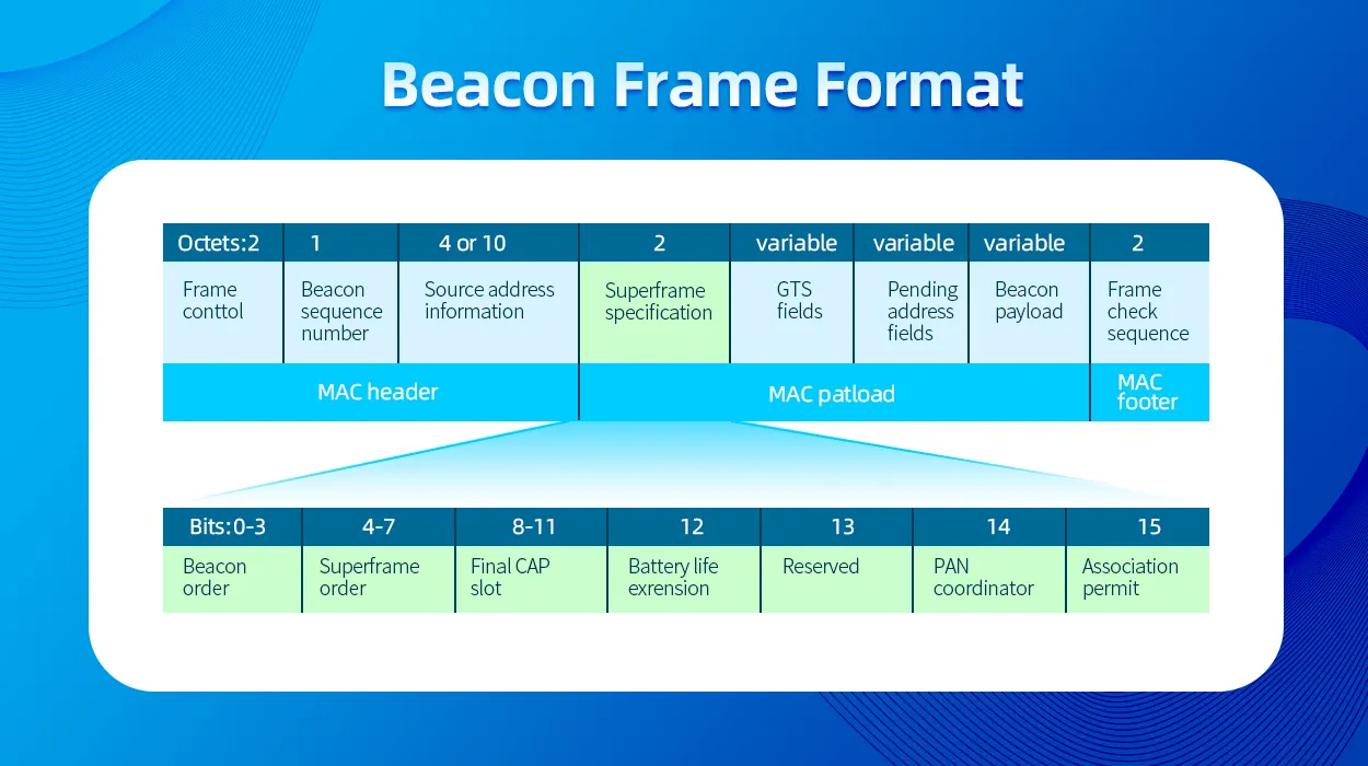
The good news is that a BLE beacon is nothing more than a small circuit that blips out a small identifier at regular intervals (Aruba beacons do so every second). It has no idea where either it or you are. Generally speaking, the payload of the beacon is very small, consisting of a major ID and a minor ID. Other ancillary data can go in there as well.
BLE Beacon Frame Format (source: Mokoblue.com)
The Major ID generally identifies the beacon type, and the Minor ID identifies the individual beacon. If you open up a BLE sniffer, you’re surrounded by beacons almost everywhere you go. Your smartphone sees all of them, but if it had to look up what every single one does, it would nuke your battery in very short order. So what happens is that when you install an application that makes use of beacons, it tells the OS (IOS or Android or whatever) that it wants to know about any beacons with a certain Major ID. The OS then asks the user if they want to allow the app to receive data about nearby network devices (IOS, I don’t know offhand how Android does it).
Once the app has permission, any time the OS sees a Major ID that has been registered by an app, it will send that beacon info to the app, which then processes the data. Apps like Meridian that do location then have information from the back end that tells it where each beacon is located, and from that, based on the signal strength of the beacon, it can multilaterate the user’s location. Waze uses this approach to provide additional location in satellite-weak areas like tunnels. But anyone with an app that knows what to do with a particular beacon can benefit from it.
Which brings me to how Apple AirTags work. Apple has done a really good job of creating an asset tracking solution that ensures the tag owner’s privacy. An AirTag is still just a BLE beacon (with some extra stuff), and the Find My app has registered the Major IDs with the OS (from the factory – and it doesn’t have any special access to the OS). Where AirTag got really clever, is the Minor ID/payload is the owner’s public key (which is unique to that specific tag). This keypair is generated when the tag is activated If it’s detected by someone other than the owner, that device takes its location (from whatever source the OS location services has), the signal strength, and the time, and encrypts that using the public key, and uploads it to Apple’s servers. Only the owner of the tag who has the private half of that key pair (stored in the device’s TPM) can decrypt the payload. And if a particular device sees someone else’s tag with a constant signal strength as the device moves around, after a while (an hour or two) it will determine that someone may be using a tag to track you and warns you. A few months ago, my daughter went on a school band trip and borrowed my suitcase, which still had an AirTag buried in it from a recent trip to Europe. About halfway across Iowa, almost 100 kids in three separate buses (including my daughter) simultaneously got an alert on their iPhones that an AirTag might be following them. They all found this incredibly amusing.
Tile’s product works in a very similar manner, but I don’t know if it does the encryption thing (which is likely patented by Apple). Apple’s product benefits from a much broader client detection base due to Find My being installed on every iPhone, so anyone with an iPhone can see and handle an AirTag. Handling a Tile beacon requires the Tile app to be installed (and some bluetooth devices like headphones are able to be located with Tile), which limits the reach. As far as I know, there’s nothing that would prevent Tile from adopting the Find My device spec. There have also been some Proof-of-Concept deployments where BLE-capable infrastructure such as Aruba Wi-Fi can also report these types of beacons back to their respective service providers.
Yesterday, I posted about leveraging the Meridian API to get a list of placemarks into a CSV file. Today, We’ll take that one step further, and go the other way – because bulk creating/updating placemarks is no fun by hand.
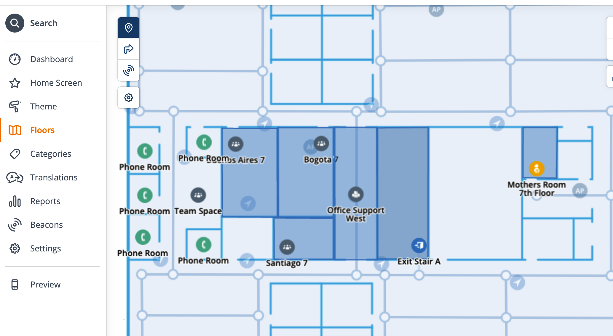
For instance, in this project, I created a bunch of placemarks called “Phone Room” (didn’t know what else to call them at the time). There were several of these on multiple floors. To rename them in the Meridian Editor, I would have to click on each one, rename it, and save.
So, once I got guidance on what they were to be called, I fired up Excel and opened up the CSV that I created yesterday, and made the changes in bulk, and then ran them back into Meridian the other way – I changed the name, the type, and the icon:
Sounds easy, right?
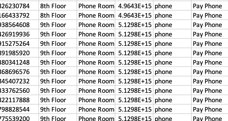
Not so much. I ran into some trouble when I opened it in excel, and all my map IDs looked like this:
This is because Excel is stupid, but trying to be smart. It sees those as Really Big Numbers, and converts them to scientific notation, because the largest it can store is a 15-digit integer. And of course, these map IDs are… 16 digits. But I can’t just convert them back as integer number formatting because it then takes the first 15 digits and adds a zero. This, of course, breaks the whole thing. Excel will also do some similar shenanigans when parsing interface names from AOS or Cisco that look like “2/1/4”, which excel assumes is a date, because excel assumes everything that looks vaguely numeric must be a number, because it is a spreadsheet after all, and spreadsheets are made for numbers, even if people abuse them all the time as a poor substitute for a database.
So, this means you either have to make the changes directly in the CSV with a text editor, or find another sheets application that doesn’t mangle the map IDs. Fortunately, for us Mac users, Apple’s spreadsheet application (“Numbers”) handles this just fine. So make the changes, export to CSV, and run it all back into the API. (you can also name it as a .txt and manually import into Excel and specify that as a text column, but that’s tedious, which is what we’re trying to avoid)
I’ve built a bit of smarts into this script, since I don’t want to break things on Meridian’s end (although Meridian does a great job of sanity checking and sanitizing the input data from the API). The first thing it does is grab a list of available maps for the location. Then it goes through all the lines in the spreadsheet, converts them to the JSON payload that Meridian wants, and checks to see if there’s existing data in the id field. If there is, it assumes that this is an update (it does not, however, check to see if the data already matches the existing placemark since Meridian does that already when you update). If there is no ID, it assumes that this is a new object to be created, and verifies that it has the minimum required information (name, map, and x/y position), and in both cases, checks to make sure the map data in the object is a map ID that exists at this location (this is how I found out that excel was mangling them)
Running the script spits out this for each row in the CSV that it considers an update:
Update object id XXXXXXXXXXXXXXX_5666694473318400
object update passed initial sanity checks and will be placed on 11th Floor.
Updating existing object with payload:
{
  "id": "XXXXXXXXXXXXXXX_5666694473318400",
  "name": "Huddle Space",
  "map": "XXXXXXXXXXXXXXX",
  "type": "conference_room",
  "type_name": "Conference Room",
  "color": "f2af1d",
  "x": "177.20516072322900",
  "y": "597.6184874989240",
  "latitude": 41.94822,
  "longitude": -87.65552,
  "area": "",
  "description": "",
  "phone": "",
  "email": "",
  "url": ""
}
Object ID XXXXXXXXXXXXXXX_5666694473318400 named Huddle Space updated on map XXXXXXXXXXXXXXXX
If it doesn’t find an id and determines that an object needs to be created, it goes down like this:
Create new object:
object create passed initial sanity checks and will be placed on 11th Floor.
Creating new object with payload:
{
  "name": "Test Placemark",
  "map": "XXXXXXXXXXXXXXXX",
  "type": "generic",
  "type_name": "Placemark",
  "color": "f2af1d",
  "x": "400",
  "y": "600",
  "latitude": "",
  "longitude": "",
  "area": "",
  "description": "",
  "phone": "",
  "email": "",
  "url": "https://arubanetworks.,com"
}
Object not created. Errors are
{
  "url": [
    "Enter a valid URL."
  ]
}
As you can see here, I made a typo in the URL field, and the data returned from the API call lists the fields that contain an error. If the call is successful, it returns an ID, which the script checks for to verify success. The response from a successful API call looks like this :
Of course, the script doesn’t have to spit out all that output, but it’s handy to follow what’s going on. Comment out the print lines if you want it to shut up.
So, without further ado, here’s the script. This has not been debugged extensively, so use at your own risk. If you break your environment, you probably should have tested it in the lab first.
#!/usr/bin/python3

# Aruba Meridian Placemark Import from CSV
# (c) 2021 Ian Beyer
# This code is not endorsed or supported by HPE

import json
import requests
import csv
import sys

auth_token = '<please insert a token to continue>'
location_id = 'XXXXXXXXXXXXXXXX'

baseurl = 'https://edit.meridianapps.com/api/locations/'+location_id


header_base = {'Authorization': 'Token '+auth_token}

def api_call(method,endpoint,headers,payload):
	response = requests.request(method, baseurl+endpoint, headers=headers, data=payload)
	resp_json = json.loads(response.text)
	return(resp_json)

#File name argument #1
try:
	fileName = str(sys.argv[1])
except:
	print("Exception: Enter file to use")
	exit()


# Get available maps for this location for sanity check
maps={}

# print("Available Maps: ")
for floor in api_call('GET','/maps',header_base,{})['results']:
 	maps[floor['id']] = floor['name']
# 	print (floor['name']+ ": "+ floor['id'])


import_data_file = open(fileName, 'rt')

csv_reader = csv.reader(import_data_file)
count = 0

objects = []

csv_fields = []

for line in csv_reader:
	placemark = {}

	# Check to see if this is the header row and capture field names
	if count < 1 :
		csv_fields = line
	else:
		# If this is a data row, capture the fields and put them into a dict object
		fcount = 0
		for fields in line:
			objkey = csv_fields[fcount]
			placemark[objkey] = line[fcount]
			fcount += 1

		# Add the placemark object into the object list
		objects.append(placemark)
	count +=1

#print(json.dumps(objects, indent=2))

import_data_file.close()

#Check imported objects for create or update. If it has an ID, then update.
for pm in objects:
	task = 'ignore'
	if pm['id'] == "" :
		task = 'create'
		print("Create new object: ")
		# Delete id from payload
		del pm['id']
	else:
		task = 'update'
		print("Update object id "+ pm['id'])


	# Remove floor from payload as it is not valid
	del pm['floor']

	# Check to see if the basics are there before making the API calls
	reject = []
	if pm['x'] == "":
		reject.append("Missing X coordinate")
	if pm['y'] == "":
		reject.append("Missing Y coordinate")
	if pm['map'] == "":
		reject.append("Missing map id")
	if pm['name'] == "":
		reject.append("Missing object name")

	if len(reject)>0:
		#print("object "+ task + " rejected due to missing required data:")
		for reason in reject:
			print(reason)
		task = 'ignore'
	else:
		if maps.get(pm['map']) == None:
			print ("Map ID "+pm['map']+" Not found in available maps. Object will not be created. ")
			task = 'ignore'
		else:
			print("object "+ task + " passed initial sanity checks and will be placed on "+ maps[pm['map']] +".")


	#print ("Object Payload:")
	#print (json.dumps(pm, indent=2))

	method = 'GET'

	if task == 'create':
		#print ("Creating new object with payload:")
		#print (json.dumps(pm, indent=2))
		method = 'POST'
		ep = '/placemarks'
		result = api_call(method,ep,header_base,pm)

		if result.get('id') != None:
			print ("Object ID "+result['id']+" named "+result['name']+ " created on map "+ result['map'])
		else:
			print ("Object not created. Errors are")
			print (json.dumps(result, indent=2))
	if task == 'update':
		#print ("Updating existing object with payload:")
		#print (json.dumps(pm, indent=2))
		method = 'PATCH'
		ep = '/placemarks/'+pm['id']
		result = api_call(method,ep,header_base,pm)

		if result.get('id') != None:
			print ("Object ID "+result['id']+" named "+result['name']+ " updated on map "+ result['map'])
		else:
			print ("Object not updated. Errors are")
			print (json.dumps(result, indent=2))


baseurl = 'https://edit.meridianapps.com/api/locations/'+location_id


header_base = {'Authorization': 'Token '+auth_token}

def api_call(method,endpoint,headers,payload):
	response = requests.request(method, baseurl+endpoint, headers=headers, data=payload)
	resp_json = json.loads(response.text)
	return(resp_json)


# Get available maps for this location for sanity check
maps={}

# print("Available Maps: ")
for floor in api_call('GET','/maps',header_base,{})['results']:
 	maps[floor['id']] = floor['name']
# 	print (floor['name']+ ": "+ floor['id'])


# I've hard coded the file name here because I'm lazy.

import_data_file = open('placemarks_update.csv', 'rt')

csv_reader = csv.reader(import_data_file)
count = 0

objects = []

csv_fields = []

for line in csv_reader:
	placemark = {}

	# Check to see if this is the header row and capture field names
	if count < 1 :
		csv_fields = line
	else:
		# If this is a data row, capture the fields and put them into a dict object
		fcount = 0
		for fields in line:
			objkey = csv_fields[fcount]
			placemark[objkey] = line[fcount]
			fcount += 1

		# Add the placemark object into the object list
		objects.append(placemark)
	count +=1

#print(json.dumps(objects, indent=2))

import_data_file.close()

#Check imported objects for create or update. If it has an ID, then update.
for pm in objects:
	task = 'ignore'
	if pm['id'] == "" :
		task = 'create'
		print("Create new object: ")
		# Delete id from payload
		del pm['id']
	else:
		task = 'update'
		print("Update object id "+ pm['id'])


	# Remove floor from payload as it is not valid
	del pm['floor']

	# Check to see if the basics are there before making the API calls
	reject = []
	if pm['x'] == "":
		reject.append("Missing X coordinate")
	if pm['y'] == "":
		reject.append("Missing Y coordinate")
	if pm['map'] == "":
		reject.append("Missing map id")
	if pm['name'] == "":
		reject.append("Missing object name")

	if len(reject)>0:
		#print("object "+ task + " rejected due to missing required data:")
		for reason in reject:
			print(reason)
		task = 'ignore'
	else:
		if maps.get(pm['map']) == None:
			print ("Map ID "+pm['map']+" Not found in available maps. Object will not be created. ")
			task = 'ignore'
		else:
			print("object "+ task + " passed initial sanity checks and will be placed on "+ maps[pm['map']] +".")


	#print ("Object Payload:")
	#print (json.dumps(pm, indent=2))

	method = 'GET'

	if task == 'create':
		#print ("Creating new object with payload:")
		#print (json.dumps(pm, indent=2))
		method = 'POST'
		ep = '/placemarks'
		result = api_call(method,ep,header_base,pm)

		if result.get('id') != None:
			print ("Object ID "+result['id']+" named "+result['name']+ " created on map "+ result['map'])
		else:
			print ("Object not created. Errors are")
			print (json.dumps(result, indent=2))
	if task == 'update':
		#print ("Updating existing object with payload:")
		#print (json.dumps(pm, indent=2))
		method = 'PATCH'
		ep = '/placemarks/'+pm['id']
		result = api_call(method,ep,header_base,pm)

		if result.get('id') != None:
			print ("Object ID "+result['id']+" named "+result['name']+ " updated on map "+ result['map'])
		else:
			print ("Object not updated. Errors are")
			print (json.dumps(result, indent=2))
It’s also worth noting here that the CSV structure and field order isn’t especially important since it reads in the header row to get the keys for the dict – as long as you have the minimum data (name/map/x/y) you can create a table of new objects from scratch. Any valid field can be used (although categories requires some additional structure)
While the web based editor is great, it is mildly annoying that one of the things it can’t do is copy and paste placemarks between floors, which would be really handy when you’re deploying an office building that has almost the same layout on every floor. For this, you have to dig into the Meridian API.
By using the API, you can spit out a list of placemarks in JSON (easiest way to do this is in Postman, with a GET to {{BaseURL}}/locations/{{LocationID}}/placemarks), grab the JSON objects for the placemarks you wish to copy from the output, update the fields in the JSON for which map ID they need to go on, and any other data, and then make a POST back to the same endpoint with a payload containing the JSON list of objects you want to create. Presto, now you’ve been able to clone all the placemarks from one floor to another.
Note that point coordinates are relative to the map image – So cloning from one map to another can bite you in the rear if they’re not properly aligned. (If you want to get really clever, You could manually create a placemark on every floor whose sole purpose is to align each floor in code – much like an alignment point in Ekahau, when you generate a placemark list, you can calculate any offsets between them and apply those to coordinates before sending them back to the API. But this trick could (and probably will) be a whole post of its own.
However, when creating a new placemark, you don’t need all these fields… The only objects that are absolutely required are map, type, x, and y (I haven’t tried sending an id along with a POST, so I don’t know if it will ignore it or reject it.) I’ve used Postman variables here for map and name, because then I could just change those in the environment variables and resubmit to put on multiple floors. The best part about the POST method is that the payload doesn’t just have to be a single JSON object, it can be a list of them, by simply putting multiple objects inside a list using square brackets.
And if you want to update an existing placemark, simply make a PATCH call to the API with the existing placemark’s ID, and whatever fields you wish to update. Like with the POST call, you can send a payload that is a list of objects This is a great way to batch update URLS or names.
It may also come in handy to generate a list of all the placemarks at a given location. So I threw together a handy little python script that will spit it out into a CSV (and will also look up the map ID and get the floor number for easy reference).
#!/usr/bin/python3

# Aruba Meridian Placemark Export to CSV
# (c) 2021 Ian Beyer
# This code is not endorsed or supported by HPE

import json
import requests
import csv
import sys

auth_token = 'Please Insert Another Token to continue playing'
location_id = 'XXXXXXXXXXXXXXXX'

baseurl = 'https://edit.meridianapps.com/api/locations/'+location_id


header_base = {'Authorization': 'Token '+auth_token}

def api_get(endpoint,headers,payload):
	response = requests.request("GET", baseurl+endpoint, headers=headers, data=payload)
	resp_json = json.loads(response.text)
	return(resp_json)

#File name argument #1
try:
	fileName = str(sys.argv[1])
except:
	print("Exception: Enter file to use")
	exit()

maps={}

for floor in api_get('/maps',header_base,{})['results']:
	maps[floor['id']] = floor['name']

beacons=[]

# Iterate by floor for easy grouping -
for flr in maps.keys():
	bcnlist=api_get('/beacons?map='+flr,header_base,{})
	# NOTE: If bcnlist['next'] is not null, then there are additional pages - this doesn't process those yet.
	for bcn in bcnlist['results']:
		# Add floor name column for easier reading.
		bcn['floor']=maps[bcn['map']]
		beacons.append(bcn)


data_file = open(fileName, 'w')
csv_writer = csv.writer(data_file)
count = 0

csv_fields = beacons[0].keys()

print(csv_fields)

csv_writer.writerow(csv_fields)

#print(placemarks)
for bcn in beacons:
	data=[]
	for col in csv_fields:
		data.append(bcn[col])
	# Writing data of CSV file
	csv_writer.writerow(data)
	count += 1
data_file.close()

print ("Exported "+str(count)+" beacons. ")
Once you have this list in a handy spreadsheet form, then you can make quick and easy edits, and then run the process the other way.
I was recently (March 2021) tasked to do a design for a small 450-seat auditorium and provide capacity and throughput numbers. Those who have known me for a while probably know that this type of auditorium is kind of a sweet spot for me, having done designs for a number of church sanctuaries of various sizes. In this post, I’m going to get into the nitty gritty details of making sure that not only does an auditorium have sufficient wireless capacity to meet the connectivity needs of the space, but also to have realistic expectations of what the performance will look like in order to build sufficient backend networking infrastructure without needlessly overbuilding it.
Auditorium design should be simple, right? Here’s how I have seen it done, way too many times to count:
Count up how many seats there are, divide by some number of seats per AP (usually based on the AP data sheet), and then figure out how many APs that gets you.
Figure out your capacity by taking the AP throughput (again from the data sheet) and multiplying that by the number of APs. Then divide that capacity so you know how much bandwidth you get per person.
Try to do a predictive model using Ekahau, to place the APs in exactly the right spot, and without ever surveying the space.
So let’s say you have a 1000-seat sanctuary where you want to use a Ubiquiti Unifi HD access point because that’s what your colleagues on social media recommended. The vendor data sheet says that you can do 500 concurrent clients per AP, so that means two APs (let’s say three just for redundancy), and each AP can do 2533 Mbps . So you should be able to get 7.6 Gbps, divided by a thousand seats, which gives you 7.6 Mbps per client, and you’ll need a 10 Gbps switch. Easy job, under a thousand bucks for the gear. And then when you fill the room up, the whole thing collapses, everyone is complaining about how it doesn’t work, and you’re left wondering why.
Because that’s not how any of this works.
For starters, never believe the data sheet. That’s marketing, not engineering. There is no amount of marketing copy that can ever overcome the fundamental laws of physics. So let’s pick this design apart, piece by piece… (yes, I’m gonna pick on Ubiquiti for a bit here, because their UniFi brand is often thrown about as a solution to all your wireless problems by people who don’t actually understand how wifi works – but these principles apply to any vendor – no vendor has a magic bullet, you still have to do the engineering)
Caution: Math (or at least some basic arithmetic and some elementary statistics) ahead. Don’t say I didn’t warn you. Hope you paid attention in school. (If you’re still in school, pay attention: you will use this stuff in real life!)
The Engineering
Winging it: Ur doin it rong.
Error #1: AP Throughput
This is probably one of the most egregious attempts by the marketing department to ignore reality. This number published on the data sheet (and also frequently wielded by consumer AP marketing) is completely bogus, but marketing loves to show off big numbers. It is typically created by taking the maximum possibly PHY rate (more on that in a second) on each radio, and adding them together. (why? you can’t aggregate client radios like that!). The number “2533 Mbps” comes from adding the max PHY on 5GHz (1733 Mbps) with the max PHY on 2.4 GHz (800 Mbps)
What is the PHY rate?
It is the speed at which an individual wireless frame is transmitted over the air. It can vary from one frame to the next, one client to the next, and is highly dependent on RF conditions. What goes into the PHY:
Channel Width
Number of MIMO Spatial Streams
Guard Interval
Modulation and Coding Scheme (MCS)
Resource Unit Size (in 802.11ax)
A table of all possible PHY rates (and the math behind them) can be found at the ever-handy mcsindex.com.
And here’s where this speed number comes flying apart. In order to achieve this maximum PHY, you need to use an 80 MHz channel (40MHz on 2.4 GHz, which is a monumentally bad idea), a short guard interval, 256QAM with 5/6 coding (which typically requires signal:noise ratio of over 40dB to achieve), and FOUR spatial streams. Given that the vast majority of devices in the wild only support two spatial streams (and the only 4SS client device is a desktop card), it’s safe to say that you’re never going to even come close to that maximum PHY rate. And even then, wireless is a half-duplex shared medium where only one device can talk on a channel at a given time. So even if you were to somehow get that max PHY, your throughput for a single device might be about half that at best. And as you add more clients, it gets even lower. Remember: Every TCP segment results in FOUR transmissions on the wireless: The segment itself, the layer 2 acknowledgement of that frame, then the TCP acknowledgement, and then the layer 2 ACK of the Layer 3 ACK.
To illustrate this, I will refer you to Aruba’s throughput test of the new AP-635, an access point that supports the 6GHz band. If marketing were to tell you the throughput of this AP, it would sound something like “3.9 Gbps” (and, in fact, the data sheet will tell you exactly that, as this is a 2×2:2 access point). But in the real world, running the widest channels on all bands, actual throughput was a bit over 2.3Gbps, and 2/3 of that was on 6GHz… Still impressive, but it also shows why you don’t actually need a 10Gbps link to it.
Error #2: Constrained Resources
The most important thing to remember when doing dense Wi-Fi deployments is that your most constrained resource is not bandwidth, it’s airtime (the amount of time a given device gets to send data). In order to maximize airtime sharing, you want devices to get on, say their piece as fast as possible, and get off. This also means you want them to use as little spectrum as possible to do so. The key to supporting more client devices is to minimize their use of spectrum and maximize spectrum reuse (where multiple access points use the same frequency in a way that they don’t interfere with each other, which is a lot harder than it sounds)
Ultimately, the only way you can add capacity to a space is to add spectrum. I’ll demonstrate in a minute how channel width matters a lot less than one might expect.
And let’s not forget that while this AP advertises throughput of 2533Mbps, it only has a 1Gbps port to connect to the switch…
Error #3: Assumptions
We’ve probably all heard the old saw about what happens when you assume something. It still holds true in wireless engineering. An auditorium may have a thousand seats, but it’s also vitally important to understand how that space is used, what kinds of devices there are, how many people, etc. Broadly speaking, an auditorium will “feel” packed and completely full when there are about two thirds of the seats occupied. But if you’re selling reserved tickets, it’s entirely possible to fill every one of those seats. And what devices are those people bringing? There’s a big difference between a 1000-seat auditorium that has 700 people in it for weekly worship and when that same space has 500 people in it attending a conference, or when 1000 people are there watching a film or a performance. Ultimately you want to plan around the most likely intensive usage scenario, which is going to typically be a conference (although I’ve done plans that assume the most intensive scenario is something completely insane like an Apple product launch).
Planning (Doing it right)
So let’s run the numbers for this fictitious auditorium that seats a thousand people. broadly speaking, this room is going to be of such a size that no matter where you place the AP, it’s going to light up the whole room. At this size, you’re not going to get any frequency reuse, even with directional antennas. If you were hoping to use the crowd to attenuate the signals and get reuse that way while putting your access points under the seats, stop now – Aruba (who have tested and deployed a whole lot of venues of all sizes) do not recommend going under the seat in any venues under about 10,000 seats unless you simply don’t have a means to go overhead.
Since we’re not getting any channel reuse, this gives us a grand total of 500 MHz of spectrum to work with, plus another 60 MHz in the 2.4GHz band – but it’s probably best to simply forget about 2.4 GHz in an auditorium because a bunch of A/V stuff is using it (and likely ill behaved stuff at that), not to mention the hundreds of wearables the people in the seats have, which will light up the entire Bluetooth channel space. So let’s go with 5 GHz for now. I’ll talk about 6GHz later.
I’m gonna go ahead and say it: Don’t waste your time with 160MHz. Sure, you get some sick PHY rates with it, but device support is limited. And don’t forget that weather radar can remove 3 channels at 20 MHz, 2 channels at 40 MHz, and 1 channel at both 80 and 160 MHz – but unless you’re very near a radar site, and the radar is penetrating from outside, you can use these channels without any issue. I’ve even seen these used inside airport terminals within view of the TDWR. Use these channels right up until you can’t.
So how do you choose what channel width to use? The only difference is whether you have more devices talking at once, at lower speeds, or fewer talking at once, but doing so at higher speeds. In the end, it doesn’t make that much of a difference to your throughput, and then it becomes a decision of how many APs you can physically put in the space (and their specific placement in a small auditorium is not too picky, since every AP lights up the entire space). 12 APs is a good flexible middle ground here, because you can do 12x40MHz channels. or 24x20MHz if the AP supports dual 5GHz radios (such as the Aruba AP-340 or AP-550 series access points), or 6x80MHz and leave the other 6 as spectrum monitors. Or adapt as needed.
Let’s now plan on a full conference load of 500 people, who each brought a laptop, a smartphone, and a tablet. and will be evenly distributed throughout the room (because elbow room and personal space). The tablet and the phone will be doing typical low-usage background stuff while the laptop will be doing much heavier usage, let’s say 1 gigabyte per hour (which is roughly equivalent to a 2Mbps video stream – I’m thinking this is something like the Church IT Network conference or the Wireless LAN Pros Conference and they’re all geeks doing geek stuff during the conference, and that about 3/4 of them are active, the rest have shut their devices off to minimize distraction. I’m also going to plan on these being 2SS MIMO devices, since that’s the overwhelming majority of what’s out there.
So here’s the breakdown, assuming most clients link up at MCS7 with a standard Gaussian distribution on either side. We’re also assuming a 50% net ratio of usable throughput (goodput) to PHY speed. Duty cycle is how much of the available airtime is used for this load – you want to try and stay under about 60% to accommodate for neighbor interference, etc. Much above that and performance really starts to suffer. These calculations are based on an Excel sheet that I have, but it’s a little rough around the edges, so I haven’t shared it here. Hit me up and I can send it to you.
24x20MHz
12x40MHz
6x80MHz
Devices
1130
1130
1130
GB/Hour
400
400
400
Available Throughput
1560
1620
1755
Duty Cycle
57%
55%
50%
Average Throughput per client
1.38 Mbps
1.43 Mbps
1.55 Mbps
And this is where things get a bit counterintuitive (as they often do with Wi-Fi): You’re slightly better off here going with fewer APs at 80 MHz than you are with more APs at 20 MHz – but if you lose an AP or a channel due to failure or radar hit, you lose a lot more capacity when using the wider channels. In any case, you can see that all you actually need for this room is a gigabit switch with a 10G uplink, and a decently fat pipe to the internet. You also need at least a /21 IP address space (but probably a good idea to go to /20 or even /19 to accommodate for MAC randomization). You also want to plan on sufficient AP capacity outside the space for devices to transition to during breaks and whatnot, but they won’t need nearly as much airtime capacity as those devices are not going to be using it as heavily as the laptops.
The Math (I warned you!)
Input data:
Infrastructure:
Area Population (Head Count) – the number of people in the room.
Distribution Curve: Normal/Gaussian
Number of access points (self-explanatory)
Channel Width (2.4GHz, 5 GHz) (Not directly used in calculations, only in determining link speed input)
Client Devices:
Wifi Devices per person (Distribution: triangular)
Gross Take Rate/how many people using wifi (Distribution: Gaussian)
% Devices on 5GHz (if using both bands)
Client Activity Modes: (activity per hour, in MB)
High/Medium/Low (Gaussian)
Activity Distribution (percentage of traffic in each mode, Gaussian)
Link Parameters (I shoot for the MCS7 values on 2SS – but what you can realistically expect will also be a function of how far the AP is from the seats, which is a factor in tall rooms):
2.4 GHz Link Speed (Mbps, median speed, triangular)
5 GHz Link Speed (Mbps, median speed, triangular)
TCP Net ratio (Goodput/Link speed, triangular)
Distribution Curves: a) Normal/Gaussian, b)Rectangular/Uniform, c) Triangular/Continuous, d) U-shaped/quadratic
Output Data:
Connected Devices: Headcount * Devices per person * Take Rate
Available Throughput (Mb/sec): AP count * Link Speed * Goodput Ratio
Duty Cycle: ((Client Demand * 8)/3600) / Available Throughput
You’ll also want to apply the distribution curves to all those values to establish your 95% confidence ranges. Hit me up if you want details..
You can also improve your airtime efficiency by narrowing the range of PHY speeds so as to keep extra slow clients from connecting and chewing up your airtime – This is accomplished by setting your basic and available data rates to a higher value such as 12 Mbps or 24 Mbps. Also, don’t forget that because any slice of airtime is at a premium, don’t go crazy with your SSIDs, to keep your beacon overhead under control even at the higher basic rates. You also don’t want to “hide” any SSIDs in order to keep your unassociated clients from chewing up airtime with probe requests that are trying to figure out if the hidden SSID is one they know about. You want as many devices in the room as you can get to associate to something, anything and shut up with the probes already. Even if it’s an open SSID that goes nowhere.
Caveats
It is worth noting here that artificially throttling client speeds will do more harm than good – the additional traffic overhead that comes with that eats up airtime like crazy. So don’t see this and think you should limit your client devices to 2Mbps in order to make sure the system doesn’t get overwhelmed – see Jim Palmer’s presentation “The Netflix Effect on Guest Wi-Fi” for why throttling client speeds doesn’t work the way you think it does. Then show it to your boss to dissuade them from insisting on meddling in the affairs of dragons.
These calculations also don’t factor in any airtime overhead from adjacent APs outside the space, which is one reason why you want to keep your airtime duty cycle under 60% and your goodput ratio to 50%. Once the system is deployed, you’ll want to validate in the field what they actually look like, which will give you a good idea of actual usage and how well the model predicted your capacity.
And, of course, all this assumes that your client devices are going to be bashing away at the network constantly, which is a fairly unusual occurrence. But you’re planning for the worst case, right? If actual usage is lower, then each client will get more throughput.
What about placement and directional antennas?
In an auditorium this size (or any size, unless it’s an arena or a stadium, that seats thousands), it really doesn’t matter. Because no matter where the AP is or what antenna it has on it, it will light up the entire room, even at a low power setting like 10dBm. Don’t get me wrong, I’m a huge fan of using directional antennas to sculpt the RF footprint. But unless you’re dealing with a small stadium, you’re not going to get frequency reuse out of directional antennas anyway (and a directional antenna can actually cause you more trouble – if the hot spot of the signal is too narrow, even way off-axis you’ll still be above the -82dBm contention backoff threshold in most of the room due to reflections and how focused your antenna is). If you want a good visual of this, go find one of the lighting people and ask them to aim a lighting fixture with a narrow beam at a seating area, turn on only that light, and vary the brightness… You’ll get enough scattered light in most of the room to see where you’re going. Light is, after all, still electromagnetic energy, so your RF is going to behave in similar ways.
Because the APs light up the whole room, you can literally put them anywhere that’s convenient for installation or maintenance access (just don’t put them too close to each other). There are however some cases where you can (and probably should) use a directional antenna in an auditorium space:
Tall ceilings – if you’re stuck with mounting the APs on a ceiling that’s much more than about 10m from the seating area, use a directional – at that height, 90° is still going to cover the entire floor, and 60° likely will too (remember that antenna beam width is considered to be between the -3dB points on the antenna plot, and in a space like an auditorium, your functional beam width is going to be closer to between the -10dB points, and you’re going to get a lot of scatter from the back lobes of the antenna as well, something that Ekahau doesn’t model – but this multipath environment can ultimately help with MIMO.
Keeping the signal inside and the noise outside – this is another place where you might consider directional antennas – if your APs are near the perimeter of the space and there’s space outside that also has Wi-Fi, a directional antenna can keep the outside signals from causing contention, as well as keep the signal from spilling into the area outside and causing contention with the APs external to the room. It’s also probably a good idea when you’re building a new auditorium to build the shell of the room such that it has high attenuation between the outside and inside (tilt-up precast concrete panels are great for this, but there’s a case to be made for intentionally designing RF shielding into the walls. It probably doesn’t hurt to set the room to a different BSS color if you’re using 802.11ax – but I haven’t yet encountered this in the wild. Last year, I was working from someone else’s design in a cruise ship where there were no fewer than 40 APs in the ship’s theatre, which seated 750. These APs were not only using a 60° directional antenna, it was placed immediately behind an expanded metal mesh used to support acoustic treatment fabric. And yet even at the lowest power I thought I could get away with, that one AP was still lighting up the seats below (about 6m away) at -60dBm… The back lobe of these antennas was bouncing off the steel structure of the ship, and the weakest spot in the room was directly on the center axis of the directional antenna. I ended up putting most of those APs in spectrum monitoring mode, and making notes for the next ship auditorium. Upside is that a steel ship gets GREAT frequency reuse elsewhere.
Aesthetics – Sometimes you just want to hide the APs – and in that situation, an external antenna can be easier to hide than a whole AP.
Note: most APs now also have BLE functionality, and because of the power levels involved, the BLE antennas are still inside the APs even if the Wi-Fi antennas are external. So if BLE is a design consideration, keep that in mind.
You can also hide APs (or antennas) by skinning them (printable automotive vinyl wrap is great for this), painting them (if the manufacturer allows this, just make sure you use nonmetallic paint), a paintable cover (Aruba offers matching paintable covers for almost all of its indoor APs) – I haven’t tried it, but I wouldn’t be surprised if you could also hydro-dip the covers or the radomes. You can also hide APs in an enclosure such as the Oberon 1019-RM or otherwise camouflage them (See previous post: Hiding In Plain Sight). But one thing you don’t want to do is put them all being the acoustic panels where they all have line of sight to each other, as this will screw with 802.11k as well as automatic channel/power algorithms like AirMatch. This is functionally the same as putting your APs above the ceiling tiles.
Too Much of a Good Thing?
If you’re dealing with a larger space where an AP doesn’t cover the entire space, check your predictive model or your survey for the number of APs visible on the band at any given location – if that number exceeds the available spectrum divided by your channel width, then you’ve got too many APs in the space (conversely, you can plan your AP coverage such that you never exceed that number (for example, 12 APs if you’re using 40MHz channels on 5GHz), you’ll maximize your spectrum reuse. You can always double up if you’re big on redundancy, but you’re not going to get any additional throughput or airtime out of it, and there are better ways to do that.
What about 802.11ax?
802.11ax (“WiFi 6”) brings a few airtime efficiencies to the table, but that will mostly manifest itself with the low traffic clients that don’t need to use the full data payload of a frame. High traffic clients will typically use all the RUs available in a single transmission, so our airtime usage calculations should not assume any OFDMA gains. BSS coloring (see above) may also be useful.
What about MU-MIMO?
Even if you have devices that support it (rare in 802.11ac, required for 802.11ax), MU-MIMO frames don’t really happen all that often in the real world, so planning your capacity around being able to use it is not a great idea. If you can somehow get MU-MIMO, then you’ll see some more efficient airtime usage. Again, we can’t count on this, so our capacity calculations should assume it isn’t happening. Once deployed, monitoring is important to see how the throughput and MU-MIMO usage actually behaves in your environment and so you can refine your calculations and models.
What about 6 GHz?
6 GHz is pretty simple – you get to add more lots more spectrum (about 3x what 5GHz offers), which directly translates to more capacity/throughput. Vendors have begun releasing tri-radio/tri-band access points (Such as the Aruba AP-630 and AP-650 series) that add the ability to run a 6 GHz radio, so you would simply calculate the additional capacity as additional APs and swap them out when the APs become available.
But also consider that client support may not be fully available for a few years, so when you run your calculations, do them for 5GHz only and then treat 6GHz as a supplemental capability. If you’re running a dozen 5 GHz APs with 40 MHz channels, you can use those same 12 APs with 80 MHz channels on 6 GHz and the higher throughput alone should encourage any 6 GHz capable client device to choose the 6 GHz connection. Band steering without the band steering.
Leave it. Pretend it doesn’t exist. An auditorium full of people is going to be chock full of Bluetooth signals from wearables and wireless earphones (not to mention an increasing number of hearing aids). There’s also a lot of A/V stuff that lives in 2.4 that you just don’t want to worry about either. If you’re unable to convince the theatrical engineers to integrate with your existing infrastructure, you may also want to leave one 20MHz channel on 5GHz for them (165 is easy). And you only gain 60 MHz of spectrum, at the expense of a lot of headache.
tl;dr
Planning your auditorium capacity isn’t just a matter of taking the vendor specs and multiplying it by a certain number of APs per seat. There’s much more detailed engineering and calculation involved, and if it’s not something you’re comfortable doing or you don’t understand the numbers, hire a pro who can do the engineering for you – it’s going to be a lot cheaper than buying the wrong thing several times over…
Let’s jump into the time machine and head back to the turn of the century (21 years ago, y’all… can you believe it?). It was a time when cable TV was king, and you could usually count on a cable outlet in almost every room of the house, when a cable TV package could easily come with half a dozen converter boxes, before the term “cord-cutter” struck fear into the hearts of cable executives. and when Netflix was an upstart DVD by mail company. This was also when a brand new technology called “Wi-Fi” had just showed up on the scene. Broadband internet (a whole 5 megabits!) was starting to find its way into homes served by cable TV, and it made dialup look severely lame. Usually these “cable modems” were hooked directly up to a single computer, either via USB, or via Ethernet if your computer was really snazzy. Often, these computers were directly connected to the internet with no firewall software, which led to all kinds of shenanigans.
Ah, those were the days.
If you had a home built around that time, chances are, the builder put coaxial cable into every room they could think of so you could have TV everywhere. And they’d usually string a daisy chained chunk of Cat5 for telephones. If they were really fancy, they would run each cable and phone outlet back to a central point where you could pick and chose where the signals went.
The challenge is that while technology changes every few years, the wiring in a house is generally put in place with little thought given to even the near future. In 2000, only the serious nerds (such as yours truly) had computers (plural) in their homes. The idea of the networked home and the Internet of Things was still a long way off.
If you were a nerd with computers (plural) and so fortunate as to have a home whose Cat5 phone cables were “home-run” back to a central interconnect (where they were usually all spliced together on a single pair for voice), you could reterminate them on both ends with a modular jack and use them for Ethernet (the idea of a router at home with NAT was still pretty new back then as well). In most cases, the runs were short enough that when gigabit Ethernet started showing up, you could still make the Cat5 work.
Recently, I had to figure out how to connect up a bunch of access points in a few homes that were built in the 1999-2000 time frame. One is the rental I just moved into, and the other is a moderately sized home owned by a client who has found himself and his family working from home a lot more lately, just like the rest of us.
My home was wired to nearly every room with home run Cat5 and coax (lucky me!). Since I have buckets full of Cat5e jacks, it was a pretty simple swap on both ends and I got gigabit. Didn’t require much effort, and thankfully didn’t require causing any damage to the rental house, which the landlord tends to get cranky about.
The client’s home, on the other hand, had daisy chained telephone line and coaxial cable throughout. And since it’s a higher end home, running ethernet cable to each room is a non-starter (not to mention expensive and disruptive). And, of course, the cable modem/router/wireless/waffle iron/juicer/vacuum combo device provided by the cable company is as far across the house from the home office as you can possibly get without actually putting it in the neighbors’ house. Cable installers love outside walls, which are about the worst possible place to put a wireless access point. Zoom calls can get a little frustrating and embarrassing when you’re the presenter and your connection sucks…
So how to get a decent connection up to the office and elsewhere in the client’s house to blanket it with wifi? Thankfully, 20 years of innovation has happened, and the chip makers and the cable companies got together to solve this problem, because they needed to deliver services over IP within the homes as well. What they came up with is the deliciously named “MoCA“, which stands for “Multimedia over Coax Alliance”. They figured out a way to be able to run a digital network signal over the existing coax wires present in most houses, and make it compatible with Ethernet.
Early versions weren’t very fast (version 1.0 in 2006 was capable of 100Mbps), but as they applied some of the same RF tricks that Wi-Fi used, they were able to make it perform at a much higher level (Version 2.5, released in 2016, is capable of 2.5Gbps). Version 3 aims to provide 10Gbps.
MoCA will support up to 16 nodes on the wire, and can coexist with some shockingly bad signal conditions. It operates from 1125MHz up to 1675MHz, which is above where cable TV signals live but still quite functional over short distances with existing coaxial cable and splitters. It forms a full mesh where each node talks directly to the other nodes that it needs to, using a combination of Time-Division Multiple Access (TDMA) and Orthogonal Frequency Division Multiple Access (OFDMA), a trick that is also used by WiFi 6/802.11ax to make better use of airtime.
MoCA also requires putting in a filter between the pole and your house so that your MoCA signals don’t end up putting your neighbors on the same network or screwing with the cable company’s lines.
Most current cable company provided gateways also support MoCA, and adding a MoCA transceiver to a live coaxial port on the wall in your house basically acts as another ethernet port on the gateway device. Cable companies commonly use this for IP based set-top boxes (over coax!) and additional wireless access points (such as Cox’s “Panoramic WiFi” and XFinity’s “XFi pods”).
While I haven’t tested the cable company’s wireless offerings (because I’m not a masochist, and I have access to vastly better wifi gear), I did want to find out how well MoCA performed as a straight Ethernet bridge for connecting up the client’s access points in such a way that I didn’t have to use wireless meshing, which performs quite poorly in most residential environments.
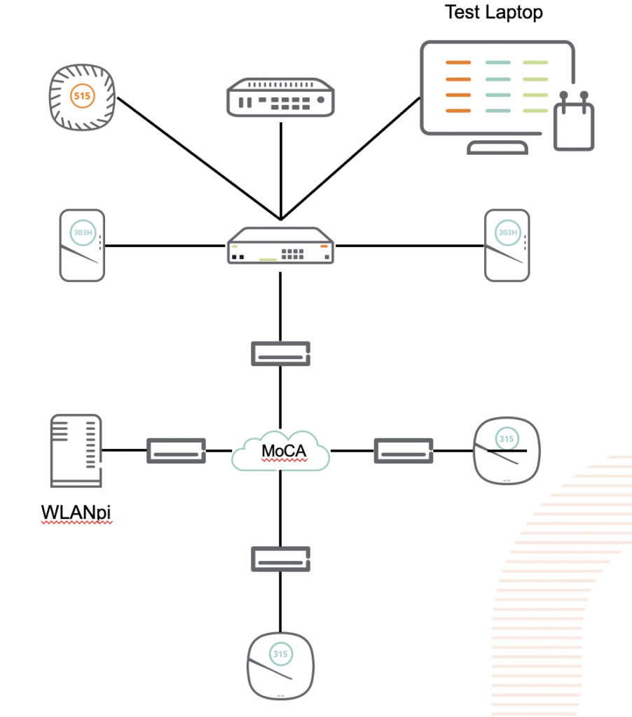
So I grabbed a couple of MoCA adapters (and a splitter) from Amazon and tried it out in a couple of different configurations. Testing was done from a MacBook Pro connected to the network via Ethernet, and a WLANpi connected on the other end of a MoCA adapter.
The test setup.
The first thing I noticed is that these devices are truly “plug and play”. I hooked one up to the coax in my office and the Ethernet side went into my switch. I then hooked 3 more up around the house, and on two of them, hooked up an access point, and on the third, the WLANpi. The access points came up and showed up in the controller just like they would on Ethernet (caveat: I had to power them externally). The WLANpi grabbed a DHCP address, and I started testing, using the librespeed web speed test built into the WLANpi, as well as iPerf3, also built into the Pi.
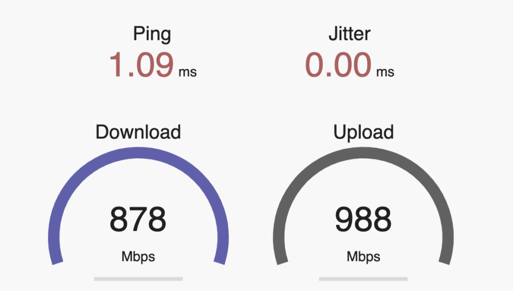
First, the baseline with the WLANpi connected directly to the switch. Pretty solid, about what you would expect from a gigabit network.
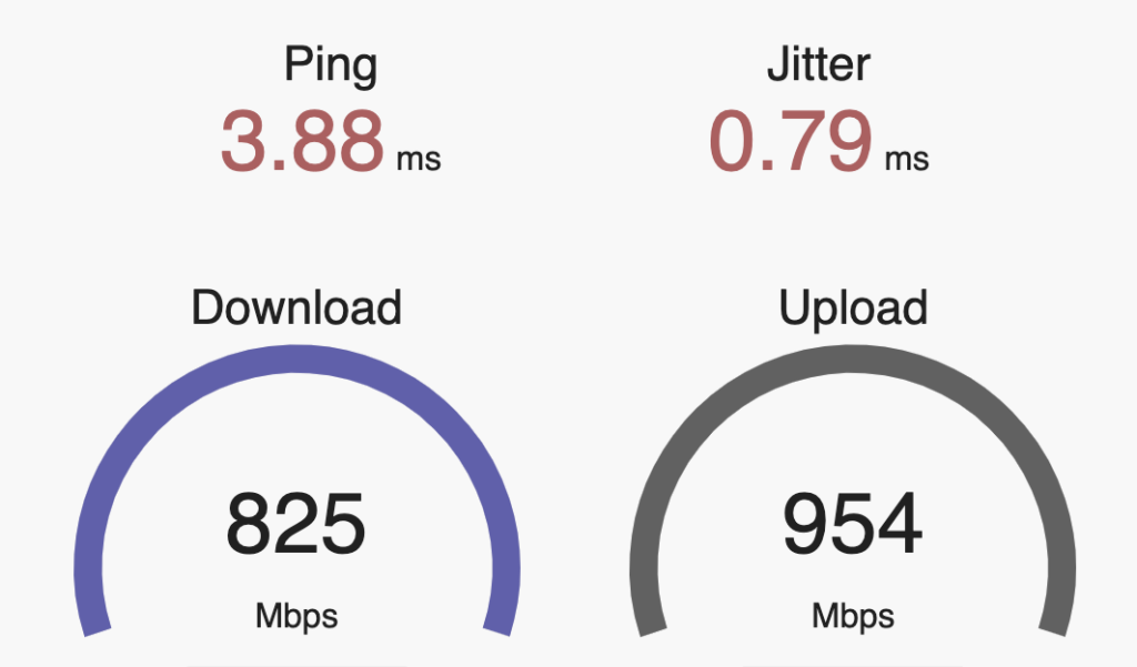
Next: The WLANpi at the other end of a 4-node MoCA 2.5 network:
An ever so slight reduction in throughput, and an extra few milliseconds of latency.
Directly connecting two nodes performed similarly.
So, bottom line, MoCA is a pretty solid option if all you have available is coax. It has the full wire speed, and doesn’t introduce the kind of latency that a wifi mesh does.
Downside: The MoCA spec doesn’t seem to provide for any means of powering converters centrally, or pushing PoE to the Ethernet device.
Other MoCA devices worth looking at:
Kiwee Broadband, has a passthru port as well as a second Ethernet port.
GoCoax, another inexpensive option that works on v2.5.
As part of trying to wrap my own head around the various profile dependencies in actually provisioning an Aruba AP , I’ve mapped it out. This is the <stuff> that goes into this process:
As you go to provision an AP, start on the outside of this map and work your way in. This will make sure that all the various profiles you need are in place. The web UI hides some of this stuff from you and doesn’t organize it as logically as one might expect.
When doing this on the CLI in Mobility Master Conductor, make sure you’re in the right corner of your hierarchy (namely, /md or /md/GROUP). And remember that on MMMCR, show run is not nearly as useful as show config effective… And config purge-pending sure comes in handy when you goof something up.
You can also do show profile-hierarchy but that only shows the profile entries and it doesn’t fit neatly in a terminal window.
Lastly, don’t forget about show references to see what other profiles reference the one you’re interested in.
Caveat: This is not comprehensive by any stretch. There are dozens more options, these are just the more common ones. If I goofed, let me know. All the gory details can be found in the ArubaOS User Guide.
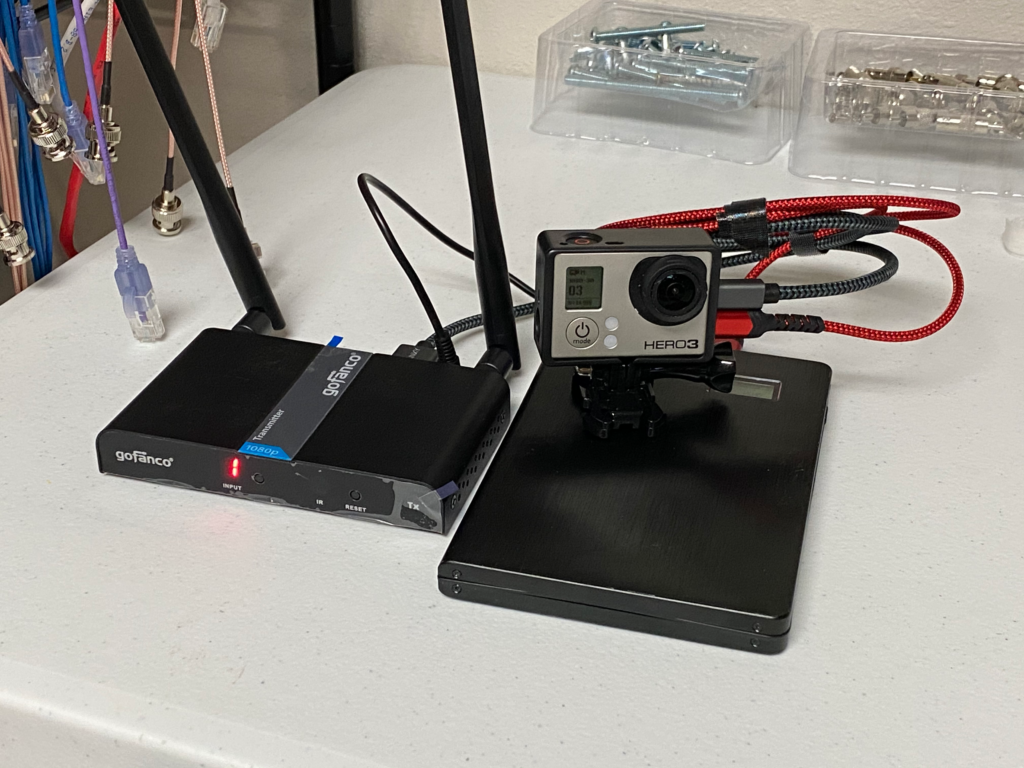
A few weeks ago, I went to Amazon and picked up a cheap wireless HDMI transmitter to solve a camera connection challenge at the church. I needed to send a GoPro feed back to the booth without running cables all over the floor (or worrying about the GoPro’s live streaming latency — it uses HLS with a real short segment size– and getting that stream into the switcher was not a trivial task).
As is so often the case with these “off-brand” (or less well-known brand) devices, my expectations were low, and I fully expected to return it after a week.
That didn’t happen. Not only was it easy to set up, the picture quality was excellent, and latency almost nonexistent. I immediately picked up another set to run a mobile confidence monitor cart. It’s also able to send IR control to the receiver.
As it turns out, GoFanco is starting to make a name for themselves in the video accessories market for both pros and consumers, not entirely unlike how BlackMagic got their start. They offer quite a wide assortment of gizmos to move video signals around.
The mobile GoPro rig. This could also potentially be used for linking live UAS footage back to a switcher.
Since I am a wireless network engineer by profession, I had significant concerns about how well this would behave in the spectrum – it advertises that it uses 5GHz, and I expected it to grab as much spectrum as it could (as most wireless video devices tend to), and walk all over everything else in the band. So I hauled out my Ekahau Sidekick and its spectrum analyzer to see how well-behaved it would be… And I was pleasantly surprised to discover that it was very well-behaved on the Wi-Fi spectrum… because it’s actually running Wi-Fi!
It’s running 802.11ac on a 20MHz channel (and the channel selection allows 10 different channels, which tells me it’s running on UNII-1 and UNII-3 and avoiding the DFS bands). Airtime usage is quite efficient, around 4%, which is shocking for a video application. And perhaps most useful is that it runs on 5VDC, and the supply is rated at 2A… Which means I can use a USB battery to power the transmitter and the GoPro (and a 20Ah slice will run this rig All. Day. Long.
Additional features allow not just 1:1 link, but 1TX:2RX, 2TX:1RX, all using a single channel. And because it’s quite efficient in spectrum/airtime usage, it does this in such a way that will coexist peacefully with your Wi-Fi.
It also means that if a presenter brings a laptop and wants to put it up on the screen, the transmitter can be powered from the laptop itself. This thing is a definitely a worthwhile addition to your tool kit.
The gory technical details,
Channel 0: Wifi Channel 36 (20MHz) (Default)
Channel 1: Wifi Channel 44 (20MHz)
Channel 2: Wifi Channel 157 (20MHz)
Channel 3: Wifi Channel 157 (40MHz)
Channel 4: Wifi Channel 149 (20MHz)
Channel 5: Wifi Channel 153 (20MHz)
Channel 6: Wifi Channel 149 (40MHz)
Channel 7: Wifi Channel 153 (40MHz)
Channel 8: Wifi Channel 165 (20MHz)
Channel 9: Wifi Channel 161 (20MHz)
This appears to be fairly smart frequency selection behaviour since these preprogrammed channels look like it will never set itself up on the secondary channel of a 40MHz pair, which is good for co-existence with other Wi-Fi. When powering up the unit, it will start on 0 but then switch to the last channel it was using once it completes booting, which only takes about 5 seconds.
Each channel is its own encrypted SSID named LK_<Channel #>.
There is a pair of LEDs on each unit: The transmitter has one that indicates it is getting a good HDMI signal, the other indicates that it has synced up with the receiver. On the receiver, one indicates that it has a good wireless signal (solid indicates a connection, blinking indicates active data transmission), and the other indicates that it has synced up with the transmitter. A mild annoyance here is that changing the channel on the receiver will not trigger the transmitter to switch channels. However, the included IR remote will let you do so. The transmitter also has an HDMI pass through, so you can insert it between a source and a monitor.
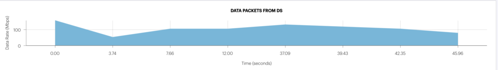
Here’s about a minute of traffic captured from the Sidekick. A channel change happens around 30 seconds in. The channel change process is pretty straightforward and exactly what you’d expect. When initiated from the receiver, it sends a deauth frame, and then the transmitter continues to beacon on its existing channel. When channel change is initiated on the transmitter, it will send a series of broadcast deauth frames to the SSID, change to the new SSID and start beaconing (this takes less than a second). Meanwhile, the receiver is looking for beacons from its pal, and when it sees the right SSID on its channel, it sends a broadcast probe request, gets the response from the transmitter, and goes through the standard association process. Management frames do not appear to be protected, so this device is vulnerable to deauth spoofing.
Data rate hovers around 100Mbps according to AristaPackets analysis of the capture. Given their use of off-the-shelf Wi-Fi for the networking component, I wouldn’t be surprised in the least to discover that the video protocol running underneath the hood was NDI, or something based on it. Why reinvent the wheel? I’d really love to crack open the encryption on this guy and see…
Given that this is using standard 802.11, the advertised range is about 50 metres, but it could easily be made to go longer distances simply by attaching a 2×2 MIMO directional antenna. Antenna connectors are RP-SMA.
One caveat: When I first set it up, the receiver was having a hard time staying up and maintaining signal… I quickly discovered that I had grabbed the wrong 5V power supply, and it was only able to source up to 1A – This device definitely needs more juice than that. Once I grabbed the correct 5V power supply, everything worked great. If you use a USB cable to power it, make sure the USB supply can source the full 2A (any supply designed for tablets or higher end smart phones should be adequate)
All in all, not a bad little setup for $200 and small change. It appears to be engineered above its price point, which is a great value.
There’s a common saying among my network engineering peers: “It’s ALWAYS DNS!”. For those not familiar with the concept, this refers to the alarming regularity with which networking troubles end up being caused by something trivial, such as name resolution. And when it’s not DNS, it’s usually DHCP. Those two troublemakers alone are responsible for some ridiculously large percentage of network support issues. (At least until someone at a tier 1 provider inserts a typo into a route table advertised to half the internet via BGP, and takes everything down, but I digress.)
Last weekend, I rebuilt my home wireless network from an Aruba Instant cluster back to a controller based network, using ClearPass as an authentication and authorization backend for the home network. Gross overkill for a home network, but it gives me stick time on stuff that I need to know for work, at a much grander scale.
But first, a little background into the Aruba Way of doing things: In an Instant cluster, the wireless networks are bridged to a VLAN that is trunked to the access point. You can also do this with campus networking, but managing all those VLANs on every port that feeds an access point is usually a recipe for forgetting something vital. So the campus model lets you build a single access VLAN on your AP ports, and the AP establishes a GRE tunnel back to the controller cluster (which also allows for some great redundancy and high availability options), and the various VLANs terminate on the user anchor controllers (because each user has their own tunnel back to the controller, which allows you to segment their traffic out and handle it at layers 4-7 based on a variety of rules, and the only thing going over the wire is an encrypted tunnel, which is a significantly better security posture should someone unethically decide to monitor traffic on a switch port when they shouldn’t.
This is also where ClearPass comes into play – How user sessions and traffic are handled is defined in roles. Each role consists of various rules. How roles are applied are defined by policies. You can map roles to users and/or machines with the magic of ClearPass, and then when someone connects to the wireless network, ClearPass can return a role (and it can map a different role based on whether you authenticated with a username/password, a certificate, or any one of a number of other data inputs). Basically, when ClearPass returns the OK to the controller, it also includes a bunch of attributes for that user, including roles. It’s extremely powerful magic, and when wielded wrong, it can cause no end of heartache trying to figure out just what exactly went haywire. And I’m still very much a ClearPass n00b.
Which brings me back to my newly built and ClearPass-enabled network. And so like every good story…
No $#!+, there I was…
When I connected, it would take a good 10 minutes before I could access the internet. And so, I’m wondering what I screwed up in my ClearPass setup that would have done this… But the roles were being assigned correctly, and the rules associated with those roles were pretty straightforward: “allow all”. So why in the heck were devices on the home network taking forever and a week to get an address? This was not happening on my IoT and guest networks.
First, I realized that my devices were associating just fine, so ClearPass and the role derivation were working correctly, which immediately acquitted the Wi-Fi (but as far as the others in my house were concerned, the Wi-Fi was still screwed up). But that meant I had a good Layer 2 connection. I tried to make sure that the VLAN was properly connected from the pfSense router to the core switch, and the controllers (running in VMWare) were properly trunking to the distributed vSwitch and also out to the core switch. Everything on that front looked good. I tried manually assigning IPs to the wireless clients on the home LAN, and they worked great. So L3 worked, which implied L2 did as well. And when clients on the home network did eventually get an IP address, they worked fine as well. So nothing was being bottlenecked anywhere either (I should hope not, as the VMWare hosts and the router are all connected to the core switch with dual 10-gigabit fiber links!).
After a few days of racking my brain over this, and hearing the people who live in my house continue to complain about network weirdness (thankfully, my family is not doing virtual school/work… except for me), I finally resigned myself to doing what I should have done in the first place: Breaking out Wireshark and figure out just what was actually happening on the network. DHCP is pretty simple, so finding out what broke should be straightforward, right?
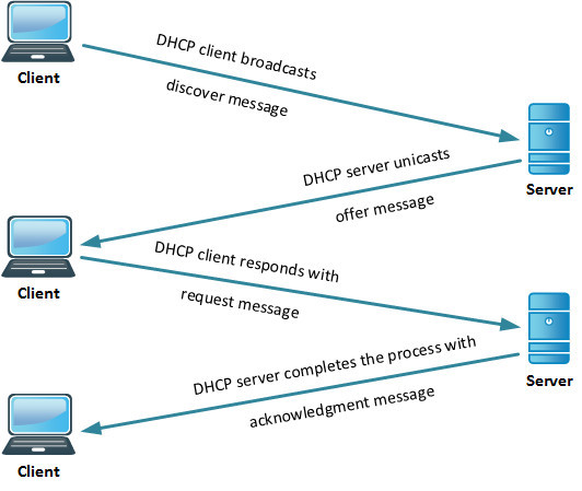
Quick refresher on DHCP: The process of obtaining a DHCP address goes like this:
Since I knew I had good L2 connectivity, I fired up Wireshark on my laptop, capturing what was going on at L2, and would move to other points in the network if I needed to. The first thing I saw is that a residential network, even with isolated guest and IoT traffic, while nobody else in the house is using it, is a fairly chatty place. I saw a bunch of multicast traffic (I have a lot of Apple devices), even IP broadcast traffic. And there, among all that, was the DHCP process. Discover. Discover. Discover. Offer. Request. Request. Request. Discover. Discover. Offer. Request. Request. Request. Discover. Discover. Discover. Offer. Request. Request. Request. The more astute among you may have noticed something missing from this sequence. Something rather… important.
Turns out, my DHCP server was making an offer, and then ghosting my devices as soon as they responded to that offer. And periodically, a DHCP ACK would sneak through. And by now, it had started happening on my IoT network as well, as half my Nest Protect alarms were now showing offline. But that told me one very important thing: that my DHCP server was in fact online, reachable, and responding. Up until that very last point.
So I then did what any sane engineer would do:
I had already restarted the dhcpd on my pfSense box, so I didn’t have much faith in the curative effects of a digital boot to the head, but what the heck, can’t hurt, right?
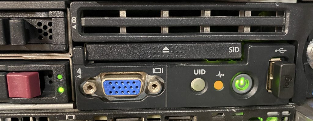
And that’s when I saw it. I went down to my lab, and there, on the front of the DL360 that is running my router, is an angry orange light which should normally be a happy little green. Uh-oh.
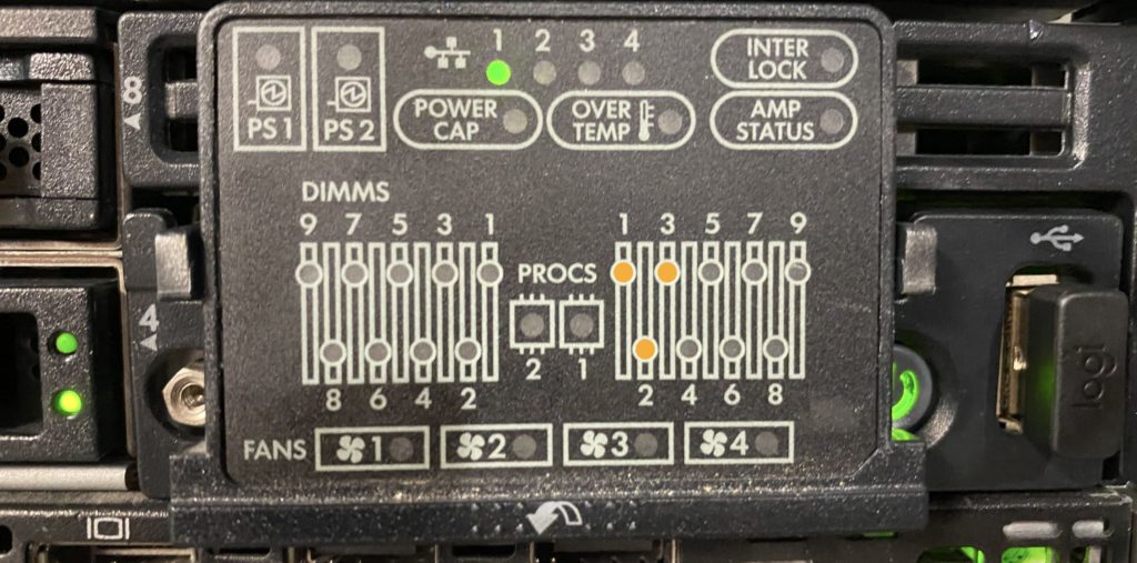
So, I pop out the handy little SID tray, to see what it’s angry about… And this is not something a server admin wants to see:
Yep, that’s flagging all three memory modules in Processor 1’s Bank A. This just became more than a simple reboot. Sure enough, when it went through POST, it flagged all three modules. Power off, slide out the server (rails FTW), and perform that tried and true troubleshooting method I learned and perfected in the Air Force a quarter century ago: Swaptronics. Move a suspected bad component and see if the problem follows. So, I switched all the DIMMs from bank A with those in Bank B. If the fault stayed with Bank A, then I had a bum system board. If the fault followed the DIMMs to Bank B, then the fault was in the DIMMs. I really wanted the fault to follow the DIMMs.
Plug it all back in, and fire it up, and the fault was…
NOW IN BANK B!!!! Hallelujah, I don’t have a bad server on my hands!
So now I shut it down, tossed the bad DIMMs in the recycling bin (yes, our recycling pickup actually takes e-waste, which is really nice when you’re a nerd with way too many electronic bits), and repopulated/balanced the banks (I also had to remove a fourth DIMM to keep things even, but it’s a known good part, so it did not go to recycling).
I fire the machine back up, and yay, it’s no longer grumpy about the bad memory, although it is briefly perplexed by the fact that it now only has 24GB instead of 32GB, and has somehow realized that it just had a partial lobotomy. After a few minutes of much more intensive self-testing than usual, it boots up pfSense, and gives me the happy beeps that pfSense does when it’s fully booted (for those of us who run our pfSense boxes headless!)
The moment of truth: I connect my laptop to the Wi-Fi (with the wireshark still circling)… and sure enough, the DHCP ACK comes through on the first try… So as near as I can tell, whatever part of the system RAM contained the bit of code required to send the DHCP ACK had suffered some kind of stroke, but not one severe enough to take the whole box or even the operating system down.
See? It’s always DHCP.
EDIT: Turns out there was also more to this – Wired clients (and access points) started getting DHCP right away after fixing this, but wireless was still giving me fits. As it turned out, There was something about the Aruba mobility controllers terminating user sessions that played havoc with the hashing algorithms that VMWare uses to handle NIC teaming on switch uplinks, and the ACKs were coming back through a different path and getting lost along the way.
For the moment, I disabled one of the 10G links to the switch until I can figure out what magic incantations I need to make on the vSwitch to get the hashing algorithms to properly use the multiple connections with the VMCs – or I may just use the second 10G interfaces for vMotion or something.
and that, kids, is how I used Wireshark to diagnose a system memory problem.