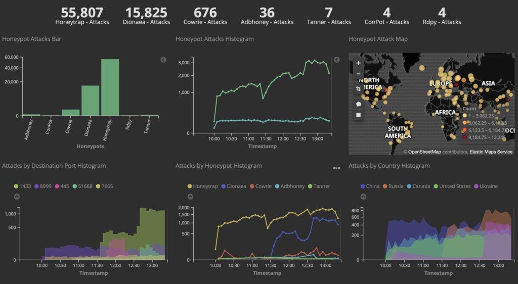
After our quick little tour of Aruba InstantON, I’m going to move up to the next level of Aruba gear: Instant.
The naming can be a little confusing to the ArubaNoob, but Instant has been part of Aruba’s product offering for a very long time. While it appears controllerless, it still makes use of a virtual controller that lives inside the APs on the network (and in case the AP running the controller goes offline, the remaining APs on the network decide on a new leader by holding a rap battle or a dance-off. OK, just kidding. They actually do a sort of digital version of Rock, Paper, Scissors, Lizard, Spock.
This virtual controller concept has also been done by Ruckus with their Unleashed platform, which in terms of functionality is somewhere between Instant and InstantON, and Cisco’s Mobility Express. I’m not 100% sure, but I think Aruba had it first.
In previous generations of Aruba access points, you either purchased an Instant AP (IAP), a Campus AP (CAP) , or a Remote AP (RAP). The latter two required a Mobility Controller (MC). You definitely couldn’t RAP without an MC. Now, all APs ship as Universal APs and figure out which mode to be when they boot up, and can be easily converted from one to the other (in the dog park that is Ruckus Unleashed, you would have to reimage the AP with new firmware).
Who it’s meant for
Instant is designed for small and medium business environments, and home labs of geeks who subscribe to the idea of “if it’s worth doing, it’s worth overdoing” (My home wireless network right now consists of 7 APs in an Instant cluster). It also is very useful in large enterprises that consist of many small locations, especially once you start managing them all with Central. If you have a chain of coffee shops or boutiques that only require a few APs, then Instant+Central is definitely something you should look at. If you only have one, InstantON is more your speed.
Instant does not require any per-AP licensing, but it still includes a lot of the features you find on the campus systems. It even includes an internal RADIUS server and user database so you can do enterprise authentication (as of 8.7 which was just released in July 2020, you can even do up to 24 unique passphrases with MPSK before having to get ClearPass involved, which is real handy for IoT networks that use crappy chipsets that don’t support enterprise auth). It will also do an internal captive portal. It still has role-based access control, which provides layer 3 policy enforcement at the AP, including content filtering. And much like the InstantON APs can do, you can even use an Instant AP as your internet gateway (guess where InstantON learned it from?). You can even use it with ClearPass and all the goodies that come with that.
When a Universal AP powers up, it goes through the following process:
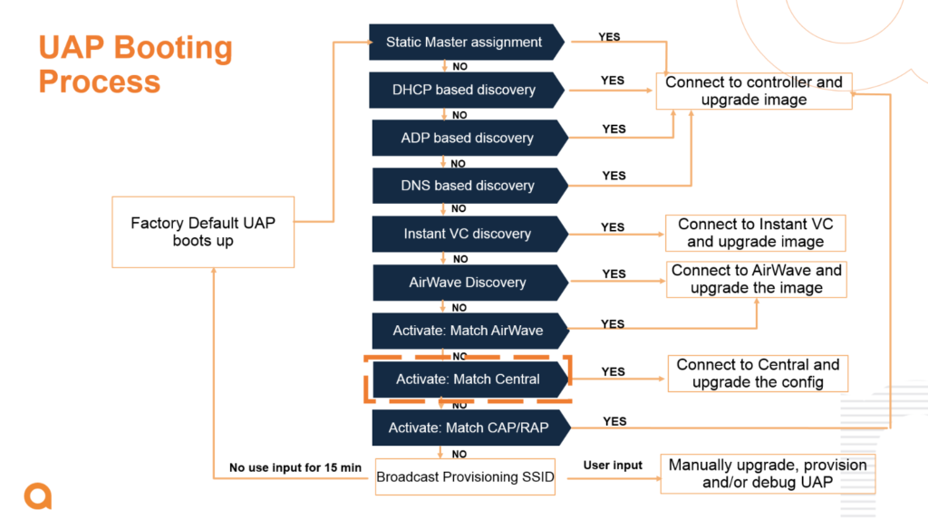
If setup mode is not accessed within a period of 15 minutes, the UAP reboots and goes through the process again. It can be a lonely existence. (this mode is not unusual to find in large campus networks where there exists a network disconnect at Layer 2 or Layer 3 between the AP and the controller. Chasing these down on a cruise ship is maddening… but it gets you a lot of steps.)
Setup Mode
Once the AP is in setup mode, it will broadcast an open SSID called SetMeUp-DD:BE:EF (where the last half is the last half of the wired MAC address of the AP). Connecting to this SSID will bring you to the configuration page (it will even conveniently pop it up in the captive portal window if your OS has such a thing). You can also access this by opening a browser to https://setmeup.arubanetworks.com, which it looks up via mDNS. (Caveat: This doesn’t work so great if the AP does not have an uplink and an IP address on the network, even if that IP is not routable… And accessing it via IP address only redirects to the hostname, and mDNS doesn’t really like not having a network to do its thing. So give it an uplink, even if it’s just a WLANpi.)
I once was traveling through a midwestern airport where I was scanning the wifi (it’s a wifi nerd thing) when I saw a lone AP broadcasting “Instant” (which is what Instant used to do before AOS 8.x). I eventually found the AP in a restaurant, where it was sitting all by itself on the ceiling, still in setup mode with the defaults… A quick peek into the setup page showed that this thing had never been configured… I found the manager to let them know that someone didn’t finish a job they were likely paid handsomely for, and she told me it had been there for almost 3 years and nobody had any idea what it was for or remembered who installed it or when. The airport’s installed public system was Meraki.
Once you’re in the setup interface, you can then configure it to your heart’s content. Then, when you bring up a second and subsequent access points on the network, they will find the first one, grab the configuration, and join the party. This scales surprisingly well – you can run several dozen access points on a network like this (There’s no actual hard limit, and it’s been officially tested up to 128 APs, but this is definitely not recommended – that’s well into Campus AP territory). It may not be truly instantaneous (we do love instant gratification), but it’s pretty darn close.
Limitations
There are a few limitations to this mode of operation, in addition to the aforementioned scaling issues (if you’re used to a SOHO/SMB system like Ubiquiti, 100 APs will sound like a lot to you. Once you get into controller based networks with Aruba, even a thousand APs is middle of the road – I routinely work with networks well in excess of this).
A few of the things you can’t do with Instant:
- AP Groups
- AirMatch (Instant uses the older ARM techniques for RF management)
- Tunneling to controller (yet…)
- I’m probably forgetting some things…
Perhaps the most useful aspect of Instant is that it can either be managed in the cloud with Aruba Central (if you’re used to Meraki, you’ll love Central), or if your network requirements grow to where you need to get a controller involved, switching the APs over to that mode is quick and easy, and you don’t have to buy new gear.
Labbing It Up
If you want to play around with Instant, it’s pretty easy: Buy an AP. Or more. If you have to fund your own lab gear, there’s a ton of used and refurbished Aruba gear on Amazon or eBay (If you go with HPE Renew, you still get HPE’s legendary lifetime warranty on network equipment). Recently, I saw a whole bunch of Renewed AP-345s on ebay for under $200. Just make sure you get the correct country code (US or RW) – the two can’t coexist on the same Instant cluster (in a controller environment, the controller country code takes over and ignores the AP setting).
If you’re new to the Aruba product line, here’s a quick cheat sheet to figure out what kind of AP you’re getting. It’s not 100% exact, but it should give you a general idea of what you should be getting.
The first digit of the 3-digit model number indicates product generation:
- AP-0XX (or just AP-XX): 802.11g
- AP-1XX: 802.11n
- AP-2XX: 802.11ac Wave 1
- AP-3XX: 802.11ac Wave 2 with integrated BLE
- AP-5XX: 802.11ax with integrated BLE and ZigBee
The second digit indicates capabilities (1XX series and up)
- AP-X0X: 2 spatial streams
- AP-X1X: 3 spatial streams (although the 51X series is 2SS on 2.4GHz and 4SS on 5GHz)
- AP-X2X: 3 spatial streams, second Ethernet port
- AP-X3X: 4 spatial streams, SmartRate port, Gigabit Port
- AP-X4X: 4 spatial streams, dual SmartRate ports, dual-5GHz,
- AP-X5X: 8 spatial streams, three radios (only AP-555 for now… that thing is a monster)
- AP-X6X: Outdoor AP with 2 Spatial streams
- AP-X7X: Outdoor AP with 4 spatial streams
- AP-X8X: Outdoor AP with 60GHz (only AP-387)
The last digit indicates the antenna type. Odd numbers are internal, even numbers are external.
- AP-XX3: Internal Omni
- AP-XX4: Connectorized
- AP-XX5: Internal Omni
- AP-XX7: Internal Directional
- AP-XX8: Connectorized and ruggedized,
APs with the H suffix indicate a wallplate mount designed for the hospitality industry. These APs also have a built-in switch. I love these APs.
Naturally, if you want to get the gory details, head on over to Aruba and look for the data sheet.
Stay tuned for the next Hands On post in which I will discuss Aruba Central.
Disclaimer: Aruba is my employer, but this post reflects my personal experience as a wi-fi nerd with Aruba products. Some APs were purchased on the open market, some were provided to me by my employer for lab use. This is not a paid promotion, and is not official Aruba communication. I am not part of the Instant product team.