Auditorium Density/Capacity Planning for Wi-Fi

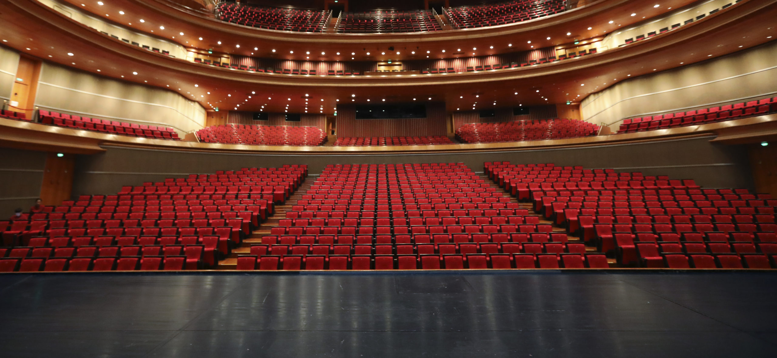
I was recently (March 2021) tasked to do a design for a small 450-seat auditorium and provide capacity and throughput numbers. Those who have known me for a while probably know that this type of auditorium is kind of a sweet spot for me, having done designs for a number of church sanctuaries of various sizes. In this post, I’m going to get into the nitty gritty details of making sure that not only does an auditorium have sufficient wireless capacity to meet the connectivity needs of the space, but also to have realistic expectations of what the performance will look like in order to build sufficient backend networking infrastructure without needlessly overbuilding it.

Auditorium design should be simple, right? Here’s how I have seen it done, way too many times to count:

  1. Count up how many seats there are, divide by some number of seats per AP (usually based on the AP data sheet), and then figure out how many APs that gets you.
  2. Figure out your capacity by taking the AP throughput (again from the data sheet) and multiplying that by the number of APs. Then divide that capacity so you know how much bandwidth you get per person.
  3. Try to do a predictive model using Ekahau, to place the APs in exactly the right spot, and without ever surveying the space.

So let’s say you have a 1000-seat sanctuary where you want to use a Ubiquiti Unifi HD access point because that’s what your colleagues on social media recommended. The vendor data sheet says that you can do 500 concurrent clients per AP, so that means two APs (let’s say three just for redundancy), and each AP can do 2533 Mbps . So you should be able to get 7.6 Gbps, divided by a thousand seats, which gives you 7.6 Mbps per client, and you’ll need a 10 Gbps switch. Easy job, under a thousand bucks for the gear. And then when you fill the room up, the whole thing collapses, everyone is complaining about how it doesn’t work, and you’re left wondering why.

Because that’s not how any of this works.

For starters, never believe the data sheet. That’s marketing, not engineering. There is no amount of marketing copy that can ever overcome the fundamental laws of physics. So let’s pick this design apart, piece by piece… (yes, I’m gonna pick on Ubiquiti for a bit here, because their UniFi brand is often thrown about as a solution to all your wireless problems by people who don’t actually understand how wifi works – but these principles apply to any vendor – no vendor has a magic bullet, you still have to do the engineering)

Caution: Math (or at least some basic arithmetic and some elementary statistics) ahead. Don’t say I didn’t warn you. Hope you paid attention in school. (If you’re still in school, pay attention: you will use this stuff in real life!)

The Engineering

Winging it: Ur doin it rong.

Error #1: AP Throughput

This is probably one of the most egregious attempts by the marketing department to ignore reality. This number published on the data sheet (and also frequently wielded by consumer AP marketing) is completely bogus, but marketing loves to show off big numbers. It is typically created by taking the maximum possibly PHY rate (more on that in a second) on each radio, and adding them together. (why? you can’t aggregate client radios like that!). The number “2533 Mbps” comes from adding the max PHY on 5GHz (1733 Mbps) with the max PHY on 2.4 GHz (800 Mbps)

What is the PHY rate?

It is the speed at which an individual wireless frame is transmitted over the air. It can vary from one frame to the next, one client to the next, and is highly dependent on RF conditions. What goes into the PHY:

  • Channel Width
  • Number of MIMO Spatial Streams
  • Guard Interval
  • Modulation and Coding Scheme (MCS)
  • Resource Unit Size (in 802.11ax)

A table of all possible PHY rates (and the math behind them) can be found at the ever-handy mcsindex.com.

And here’s where this speed number comes flying apart. In order to achieve this maximum PHY, you need to use an 80 MHz channel (40MHz on 2.4 GHz, which is a monumentally bad idea), a short guard interval, 256QAM with 5/6 coding (which typically requires signal:noise ratio of over 40dB to achieve), and FOUR spatial streams. Given that the vast majority of devices in the wild only support two spatial streams (and the only 4SS client device is a desktop card), it’s safe to say that you’re never going to even come close to that maximum PHY rate. And even then, wireless is a half-duplex shared medium where only one device can talk on a channel at a given time. So even if you were to somehow get that max PHY, your throughput for a single device might be about half that at best. And as you add more clients, it gets even lower. Remember: Every TCP segment results in FOUR transmissions on the wireless: The segment itself, the layer 2 acknowledgement of that frame, then the TCP acknowledgement, and then the layer 2 ACK of the Layer 3 ACK.

To illustrate this, I will refer you to Aruba’s throughput test of the new AP-635, an access point that supports the 6GHz band. If marketing were to tell you the throughput of this AP, it would sound something like “3.9 Gbps” (and, in fact, the data sheet will tell you exactly that, as this is a 2×2:2 access point). But in the real world, running the widest channels on all bands, actual throughput was a bit over 2.3Gbps, and 2/3 of that was on 6GHz… Still impressive, but it also shows why you don’t actually need a 10Gbps link to it.

Error #2: Constrained Resources

The most important thing to remember when doing dense Wi-Fi deployments is that your most constrained resource is not bandwidth, it’s airtime (the amount of time a given device gets to send data). In order to maximize airtime sharing, you want devices to get on, say their piece as fast as possible, and get off. This also means you want them to use as little spectrum as possible to do so. The key to supporting more client devices is to minimize their use of spectrum and maximize spectrum reuse (where multiple access points use the same frequency in a way that they don’t interfere with each other, which is a lot harder than it sounds)

Ultimately, the only way you can add capacity to a space is to add spectrum. I’ll demonstrate in a minute how channel width matters a lot less than one might expect.

And let’s not forget that while this AP advertises throughput of 2533Mbps, it only has a 1Gbps port to connect to the switch…

Error #3: Assumptions

We’ve probably all heard the old saw about what happens when you assume something. It still holds true in wireless engineering. An auditorium may have a thousand seats, but it’s also vitally important to understand how that space is used, what kinds of devices there are, how many people, etc. Broadly speaking, an auditorium will “feel” packed and completely full when there are about two thirds of the seats occupied. But if you’re selling reserved tickets, it’s entirely possible to fill every one of those seats. And what devices are those people bringing? There’s a big difference between a 1000-seat auditorium that has 700 people in it for weekly worship and when that same space has 500 people in it attending a conference, or when 1000 people are there watching a film or a performance. Ultimately you want to plan around the most likely intensive usage scenario, which is going to typically be a conference (although I’ve done plans that assume the most intensive scenario is something completely insane like an Apple product launch).

Planning (Doing it right)

So let’s run the numbers for this fictitious auditorium that seats a thousand people. broadly speaking, this room is going to be of such a size that no matter where you place the AP, it’s going to light up the whole room. At this size, you’re not going to get any frequency reuse, even with directional antennas. If you were hoping to use the crowd to attenuate the signals and get reuse that way while putting your access points under the seats, stop now – Aruba (who have tested and deployed a whole lot of venues of all sizes) do not recommend going under the seat in any venues under about 10,000 seats unless you simply don’t have a means to go overhead.

Since we’re not getting any channel reuse, this gives us a grand total of 500 MHz of spectrum to work with, plus another 60 MHz in the 2.4GHz band – but it’s probably best to simply forget about 2.4 GHz in an auditorium because a bunch of A/V stuff is using it (and likely ill behaved stuff at that), not to mention the hundreds of wearables the people in the seats have, which will light up the entire Bluetooth channel space. So let’s go with 5 GHz for now. I’ll talk about 6GHz later.

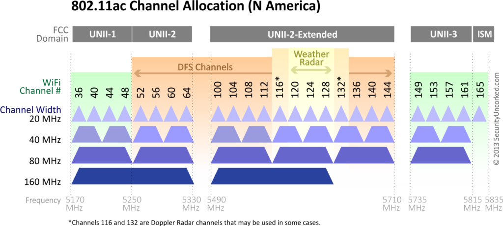
In the 5 GHz band, we have:

  • 25 channels at 20 MHz (500 MHz)
  • 12 channels at 40 MHz (480 MHz)
  • 6 channels at 80 MHz (480 MHz)
  • 2 channels at 160 MHz (320 MHz)
5 GHz Channel Allocation (Credit: Jennifer Minella, SecurityUncorked.com)

I’m gonna go ahead and say it: Don’t waste your time with 160MHz. Sure, you get some sick PHY rates with it, but device support is limited. And don’t forget that weather radar can remove 3 channels at 20 MHz, 2 channels at 40 MHz, and 1 channel at both 80 and 160 MHz – but unless you’re very near a radar site, and the radar is penetrating from outside, you can use these channels without any issue. I’ve even seen these used inside airport terminals within view of the TDWR. Use these channels right up until you can’t.

So how do you choose what channel width to use? The only difference is whether you have more devices talking at once, at lower speeds, or fewer talking at once, but doing so at higher speeds. In the end, it doesn’t make that much of a difference to your throughput, and then it becomes a decision of how many APs you can physically put in the space (and their specific placement in a small auditorium is not too picky, since every AP lights up the entire space). 12 APs is a good flexible middle ground here, because you can do 12x40MHz channels. or 24x20MHz if the AP supports dual 5GHz radios (such as the Aruba AP-340 or AP-550 series access points), or 6x80MHz and leave the other 6 as spectrum monitors. Or adapt as needed.

Let’s now plan on a full conference load of 500 people, who each brought a laptop, a smartphone, and a tablet. and will be evenly distributed throughout the room (because elbow room and personal space). The tablet and the phone will be doing typical low-usage background stuff while the laptop will be doing much heavier usage, let’s say 1 gigabyte per hour (which is roughly equivalent to a 2Mbps video stream – I’m thinking this is something like the Church IT Network conference or the Wireless LAN Pros Conference and they’re all geeks doing geek stuff during the conference, and that about 3/4 of them are active, the rest have shut their devices off to minimize distraction. I’m also going to plan on these being 2SS MIMO devices, since that’s the overwhelming majority of what’s out there.

So here’s the breakdown, assuming most clients link up at MCS7 with a standard Gaussian distribution on either side. We’re also assuming a 50% net ratio of usable throughput (goodput) to PHY speed. Duty cycle is how much of the available airtime is used for this load – you want to try and stay under about 60% to accommodate for neighbor interference, etc. Much above that and performance really starts to suffer. These calculations are based on an Excel sheet that I have, but it’s a little rough around the edges, so I haven’t shared it here. Hit me up and I can send it to you.

24x20MHz12x40MHz6x80MHz
Devices113011301130
GB/Hour400400400
Available Throughput156016201755
Duty Cycle57%55%50%
Average Throughput per client1.38 Mbps1.43 Mbps1.55 Mbps

And this is where things get a bit counterintuitive (as they often do with Wi-Fi): You’re slightly better off here going with fewer APs at 80 MHz than you are with more APs at 20 MHz – but if you lose an AP or a channel due to failure or radar hit, you lose a lot more capacity when using the wider channels. In any case, you can see that all you actually need for this room is a gigabit switch with a 10G uplink, and a decently fat pipe to the internet. You also need at least a /21 IP address space (but probably a good idea to go to /20 or even /19 to accommodate for MAC randomization). You also want to plan on sufficient AP capacity outside the space for devices to transition to during breaks and whatnot, but they won’t need nearly as much airtime capacity as those devices are not going to be using it as heavily as the laptops.

The Math (I warned you!)

Input data:
  • Infrastructure:
    • Area Population (Head Count) – the number of people in the room.
    • Distribution Curve: Normal/Gaussian
    • Number of access points (self-explanatory)
    • Channel Width (2.4GHz, 5 GHz) (Not directly used in calculations, only in determining link speed input)
  • Client Devices:
    • Wifi Devices per person (Distribution: triangular)
    • Gross Take Rate/how many people using wifi (Distribution: Gaussian)
    • % Devices on 5GHz (if using both bands)
  • Client Activity Modes: (activity per hour, in MB)
    • High/Medium/Low (Gaussian)
  • Activity Distribution (percentage of traffic in each mode, Gaussian)
  • Link Parameters (I shoot for the MCS7 values on 2SS – but what you can realistically expect will also be a function of how far the AP is from the seats, which is a factor in tall rooms):
    • 2.4 GHz Link Speed (Mbps, median speed, triangular)
    • 5 GHz Link Speed (Mbps, median speed, triangular)
    • TCP Net ratio (Goodput/Link speed, triangular)
Distribution Curves: a) Normal/Gaussian, b)Rectangular/Uniform, c) Triangular/Continuous, d) U-shaped/quadratic
Output Data:
  • Connected Devices: Headcount * Devices per person * Take Rate
  • Client Demand (MB/hr): (Sum of: (activity mode * activity percentage)) * headcount
  • Available Throughput (Mb/sec): AP count * Link Speed * Goodput Ratio
  • Duty Cycle: ((Client Demand * 8)/3600) / Available Throughput

You’ll also want to apply the distribution curves to all those values to establish your 95% confidence ranges. Hit me up if you want details..

You can also improve your airtime efficiency by narrowing the range of PHY speeds so as to keep extra slow clients from connecting and chewing up your airtime – This is accomplished by setting your basic and available data rates to a higher value such as 12 Mbps or 24 Mbps. Also, don’t forget that because any slice of airtime is at a premium, don’t go crazy with your SSIDs, to keep your beacon overhead under control even at the higher basic rates. You also don’t want to “hide” any SSIDs in order to keep your unassociated clients from chewing up airtime with probe requests that are trying to figure out if the hidden SSID is one they know about. You want as many devices in the room as you can get to associate to something, anything and shut up with the probes already. Even if it’s an open SSID that goes nowhere.

Caveats

It is worth noting here that artificially throttling client speeds will do more harm than good – the additional traffic overhead that comes with that eats up airtime like crazy. So don’t see this and think you should limit your client devices to 2Mbps in order to make sure the system doesn’t get overwhelmed – see Jim Palmer’s presentation “The Netflix Effect on Guest Wi-Fi” for why throttling client speeds doesn’t work the way you think it does. Then show it to your boss to dissuade them from insisting on meddling in the affairs of dragons.

These calculations also don’t factor in any airtime overhead from adjacent APs outside the space, which is one reason why you want to keep your airtime duty cycle under 60% and your goodput ratio to 50%. Once the system is deployed, you’ll want to validate in the field what they actually look like, which will give you a good idea of actual usage and how well the model predicted your capacity.

And, of course, all this assumes that your client devices are going to be bashing away at the network constantly, which is a fairly unusual occurrence. But you’re planning for the worst case, right? If actual usage is lower, then each client will get more throughput.

What about placement and directional antennas?

In an auditorium this size (or any size, unless it’s an arena or a stadium, that seats thousands), it really doesn’t matter. Because no matter where the AP is or what antenna it has on it, it will light up the entire room, even at a low power setting like 10dBm. Don’t get me wrong, I’m a huge fan of using directional antennas to sculpt the RF footprint. But unless you’re dealing with a small stadium, you’re not going to get frequency reuse out of directional antennas anyway (and a directional antenna can actually cause you more trouble – if the hot spot of the signal is too narrow, even way off-axis you’ll still be above the -82dBm contention backoff threshold in most of the room due to reflections and how focused your antenna is). If you want a good visual of this, go find one of the lighting people and ask them to aim a lighting fixture with a narrow beam at a seating area, turn on only that light, and vary the brightness… You’ll get enough scattered light in most of the room to see where you’re going. Light is, after all, still electromagnetic energy, so your RF is going to behave in similar ways.

Because the APs light up the whole room, you can literally put them anywhere that’s convenient for installation or maintenance access (just don’t put them too close to each other). There are however some cases where you can (and probably should) use a directional antenna in an auditorium space:

Tall ceilings – if you’re stuck with mounting the APs on a ceiling that’s much more than about 10m from the seating area, use a directional – at that height, 90° is still going to cover the entire floor, and 60° likely will too (remember that antenna beam width is considered to be between the -3dB points on the antenna plot, and in a space like an auditorium, your functional beam width is going to be closer to between the -10dB points, and you’re going to get a lot of scatter from the back lobes of the antenna as well, something that Ekahau doesn’t model – but this multipath environment can ultimately help with MIMO.

Keeping the signal inside and the noise outside – this is another place where you might consider directional antennas – if your APs are near the perimeter of the space and there’s space outside that also has Wi-Fi, a directional antenna can keep the outside signals from causing contention, as well as keep the signal from spilling into the area outside and causing contention with the APs external to the room. It’s also probably a good idea when you’re building a new auditorium to build the shell of the room such that it has high attenuation between the outside and inside (tilt-up precast concrete panels are great for this, but there’s a case to be made for intentionally designing RF shielding into the walls. It probably doesn’t hurt to set the room to a different BSS color if you’re using 802.11ax – but I haven’t yet encountered this in the wild. Last year, I was working from someone else’s design in a cruise ship where there were no fewer than 40 APs in the ship’s theatre, which seated 750. These APs were not only using a 60° directional antenna, it was placed immediately behind an expanded metal mesh used to support acoustic treatment fabric. And yet even at the lowest power I thought I could get away with, that one AP was still lighting up the seats below (about 6m away) at -60dBm… The back lobe of these antennas was bouncing off the steel structure of the ship, and the weakest spot in the room was directly on the center axis of the directional antenna. I ended up putting most of those APs in spectrum monitoring mode, and making notes for the next ship auditorium. Upside is that a steel ship gets GREAT frequency reuse elsewhere.

Aesthetics – Sometimes you just want to hide the APs – and in that situation, an external antenna can be easier to hide than a whole AP.

Note: most APs now also have BLE functionality, and because of the power levels involved, the BLE antennas are still inside the APs even if the Wi-Fi antennas are external. So if BLE is a design consideration, keep that in mind.

You can also hide APs (or antennas) by skinning them (printable automotive vinyl wrap is great for this), painting them (if the manufacturer allows this, just make sure you use nonmetallic paint), a paintable cover (Aruba offers matching paintable covers for almost all of its indoor APs) – I haven’t tried it, but I wouldn’t be surprised if you could also hydro-dip the covers or the radomes. You can also hide APs in an enclosure such as the Oberon 1019-RM or otherwise camouflage them (See previous post: Hiding In Plain Sight). But one thing you don’t want to do is put them all being the acoustic panels where they all have line of sight to each other, as this will screw with 802.11k as well as automatic channel/power algorithms like AirMatch. This is functionally the same as putting your APs above the ceiling tiles.

Too Much of a Good Thing?

If you’re dealing with a larger space where an AP doesn’t cover the entire space, check your predictive model or your survey for the number of APs visible on the band at any given location – if that number exceeds the available spectrum divided by your channel width, then you’ve got too many APs in the space (conversely, you can plan your AP coverage such that you never exceed that number (for example, 12 APs if you’re using 40MHz channels on 5GHz), you’ll maximize your spectrum reuse. You can always double up if you’re big on redundancy, but you’re not going to get any additional throughput or airtime out of it, and there are better ways to do that.

What about 802.11ax?

802.11ax (“WiFi 6”) brings a few airtime efficiencies to the table, but that will mostly manifest itself with the low traffic clients that don’t need to use the full data payload of a frame. High traffic clients will typically use all the RUs available in a single transmission, so our airtime usage calculations should not assume any OFDMA gains. BSS coloring (see above) may also be useful.

What about MU-MIMO?

Even if you have devices that support it (rare in 802.11ac, required for 802.11ax), MU-MIMO frames don’t really happen all that often in the real world, so planning your capacity around being able to use it is not a great idea. If you can somehow get MU-MIMO, then you’ll see some more efficient airtime usage. Again, we can’t count on this, so our capacity calculations should assume it isn’t happening. Once deployed, monitoring is important to see how the throughput and MU-MIMO usage actually behaves in your environment and so you can refine your calculations and models.

What about 6 GHz?

6 GHz is pretty simple – you get to add more lots more spectrum (about 3x what 5GHz offers), which directly translates to more capacity/throughput. Vendors have begun releasing tri-radio/tri-band access points (Such as the Aruba AP-630 and AP-650 series) that add the ability to run a 6 GHz radio, so you would simply calculate the additional capacity as additional APs and swap them out when the APs become available.

But also consider that client support may not be fully available for a few years, so when you run your calculations, do them for 5GHz only and then treat 6GHz as a supplemental capability. If you’re running a dozen 5 GHz APs with 40 MHz channels, you can use those same 12 APs with 80 MHz channels on 6 GHz and the higher throughput alone should encourage any 6 GHz capable client device to choose the 6 GHz connection. Band steering without the band steering.
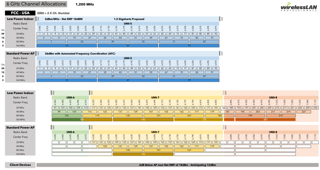
6GHz Wi-Fi Spectrum (Image Credit: Wireless LAN Professionals)

What about 2.4 GHz?

Leave it. Pretend it doesn’t exist. An auditorium full of people is going to be chock full of Bluetooth signals from wearables and wireless earphones (not to mention an increasing number of hearing aids). There’s also a lot of A/V stuff that lives in 2.4 that you just don’t want to worry about either. If you’re unable to convince the theatrical engineers to integrate with your existing infrastructure, you may also want to leave one 20MHz channel on 5GHz for them (165 is easy). And you only gain 60 MHz of spectrum, at the expense of a lot of headache.

tl;dr

Planning your auditorium capacity isn’t just a matter of taking the vendor specs and multiplying it by a certain number of APs per seat. There’s much more detailed engineering and calculation involved, and if it’s not something you’re comfortable doing or you don’t understand the numbers, hire a pro who can do the engineering for you – it’s going to be a lot cheaper than buying the wrong thing several times over…

Additional Resources

Props and Shout-Outs

Thanks to the following people who contributed their expertise and knowledge to this post:

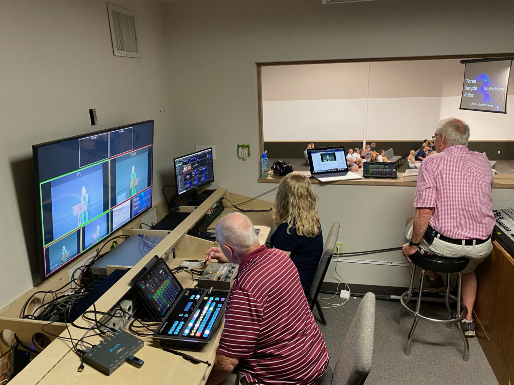
Video Production Suite

I’m going to veer off from my usual diet of wireless posts to bring you a howto post on the new video production desk that I built for the Family Life Center at our church.

Over the past year, we’ve been putting together a major upgrade to the video equipment in the FLC, because this is what we had…

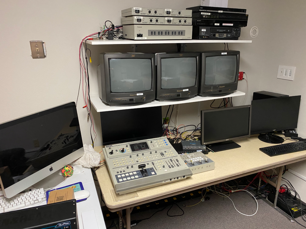
Tech Booth with 1980s vintage video equipment

If you’re young, you may not recognize some of this. That switcher is a Panasonic AG-MX50, coupled with a 3-camera PTZ system of the same era. The AG-MX50 was introduced sometime around 1990, and quickly gained popularity not just for live production, but for anyone doing tape to tape edits – I first used this same system when working in the A/V department in college, and it was a pretty slick piece of kit then. Our FLC was built in 2002, and eventually inherited this video system from the sanctuary when it was upgraded several years back. To say that this system is past its prime would be a gross understatement.

The projectors in the room were also getting on in years, and in dire need of replacement. So we looked at what we needed to bring the video in our most attended venue into the 21st Century, and continuing a video ministry that has been in operation since the mid-1970s.

Background: We are a United Methodist church in a county seat town in central Kansas – about 250 a week in worship between two venues – while that’s big by United Methodist standards, we’re not one of these big high-tech churches – we do a lot with a little. (Long-time readers of the blog will remember that I worked at one of those big high-tech churches about a decade ago… It’s remarkable how much of those ideas can be scaled down to a “normal” sized church. The overall project budget for this video upgrade was under $40,000, and we included in that about 20-25% wiggle room for random cables, connectivity, and, apparently, building furniture. That little stuff adds up after a while.

The first piece was to add a couple of 75″ TVs (Samsung 7 series) in the front of the room on either side of the stage. This allowed people sitting in front to see what was on the screens, which were roughly even with the first row of seating. Our existing projectors were running 4:3 off a VGA signal that was being split and amplified and sent over some heavy duty cables to the projectors. The TVs didn’t support any kind of analog input, so I ran some Belden 9116 RG6 cable and put a Decimator MD-HX on the computer end, and a couple of BlackMagic HDMI converters at the TVs, and a WiiStar VGA converter on the projectors, as well as an SDI to analog converter for the switcher running the stream. Later, when we added the new projectors (Panasonic PT-VMZ60), I put a Decimator MD-LX to get the signal to HDMI. the Projectors and TVs were daisy-chained on the SDI link.

The next piece of the puzzle was to upgrade our switcher – We started with a BlackMagic ATEM TV Studio, and added a couple of WiiStar analog to SDI converters, but the ATEM TVS is rather finicky about input formats, which only one of the converters managed to output correctly. So we ran the SDI from the Decimator into the TVS, and then used an analog to SDI converter to get the output of the analog switcher into the TVS as well, and switched using both. This is also when we added an Aja Helo encoder to the mix, as my Teradek VidiU (a demo from the vendor) had decided to call it quits.

After several months of this, the funds were finally available to purchase the Ross Carbonite Solo switcher we had decided upon (cheaper than the ATEM 1ME unit, with more features, but most importantly, it had 6 build in scan converters, meaning I wouldn’t have to get a small platoon of Decimator MD-HX units just to make the ATEM happy. We opted for the 9-input unit rather than the 13, as this was plenty for our needs. We also purchased the AW-RP150 camera controller so we’d be ready when the funds came in for the new cameras – We had to replace a lot of infrastructure in order to be ready for the cameras.

Naturally, this meant we were going to have to make a major update to our workspace – as you can see above, it was kind of cluttered and not very functional. So I set about making a custom desk that would accommodate all the gear, keeping cable messes out of sight, and making the overall system much more user-friendly.

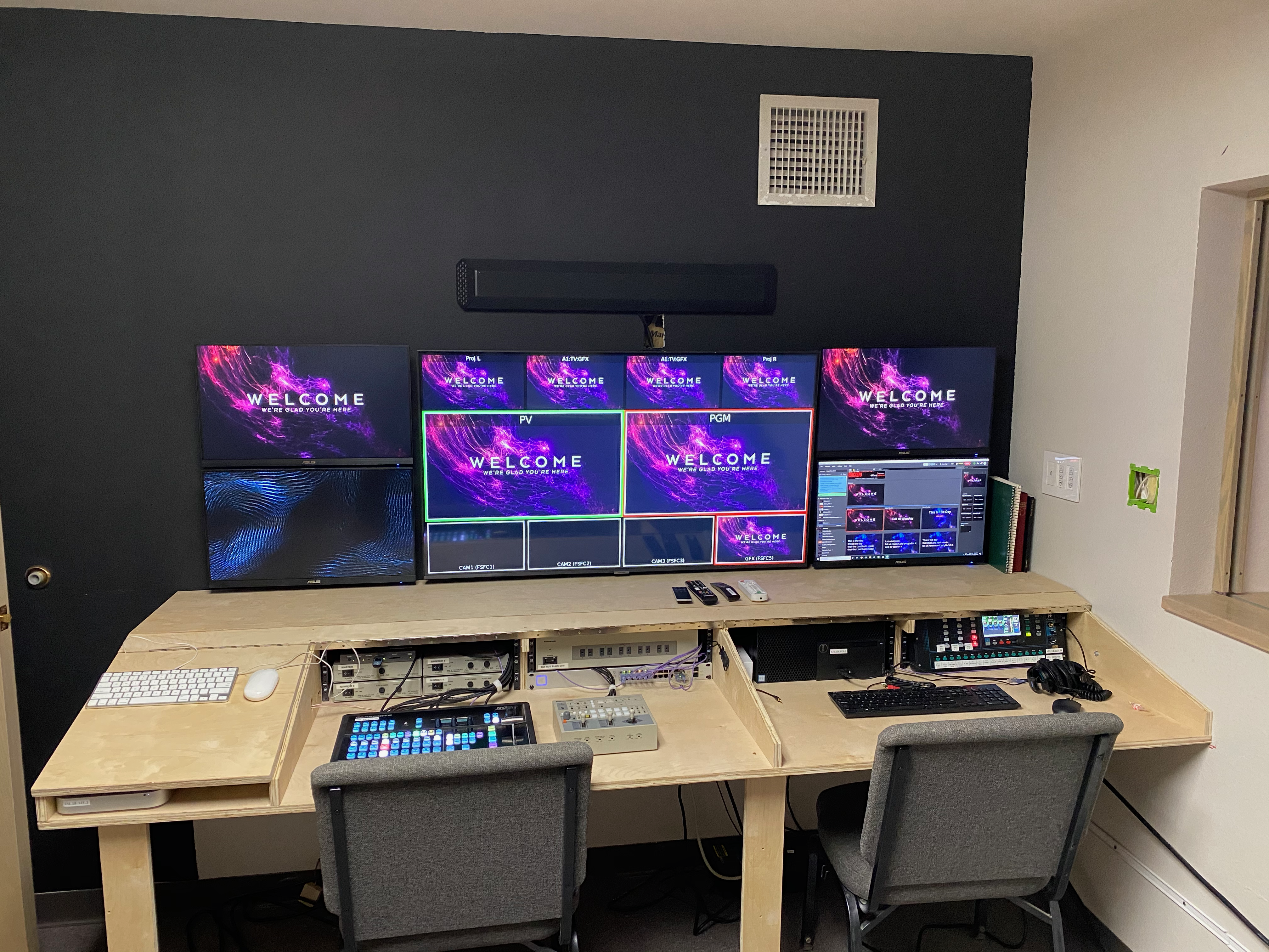
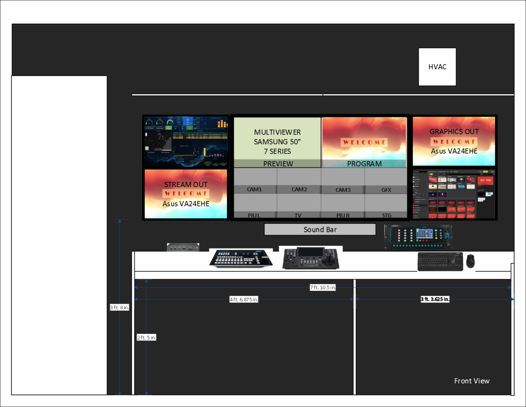
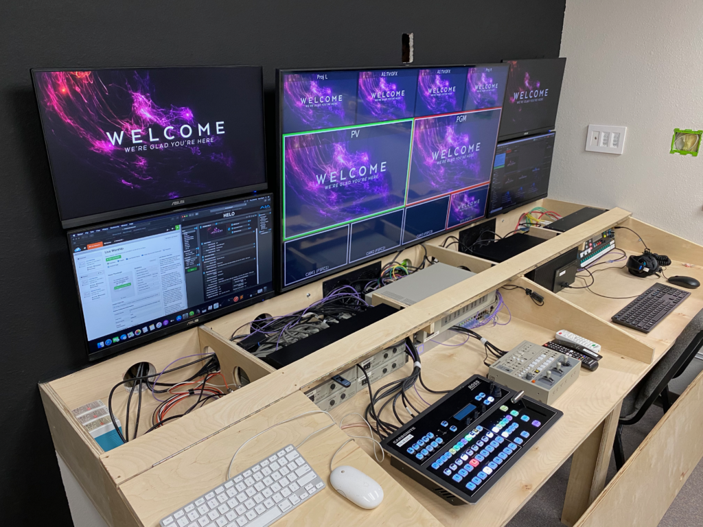
I then considered the overall layout and found that a 50″ TV as a central multiviewer with two 24″ monitors stacked on either side would give us an array of displays that would give us a good overview of the production. I had initially planned on mounting it about 8″ above the surface of the desk, but that ended up being a lot less ergonomic than we had figured, so I ended up moving them down almost flush with the flat surface of the desk, meaning I had to mount the sound bar above (suboptimal, but functional).

A rough early layout.

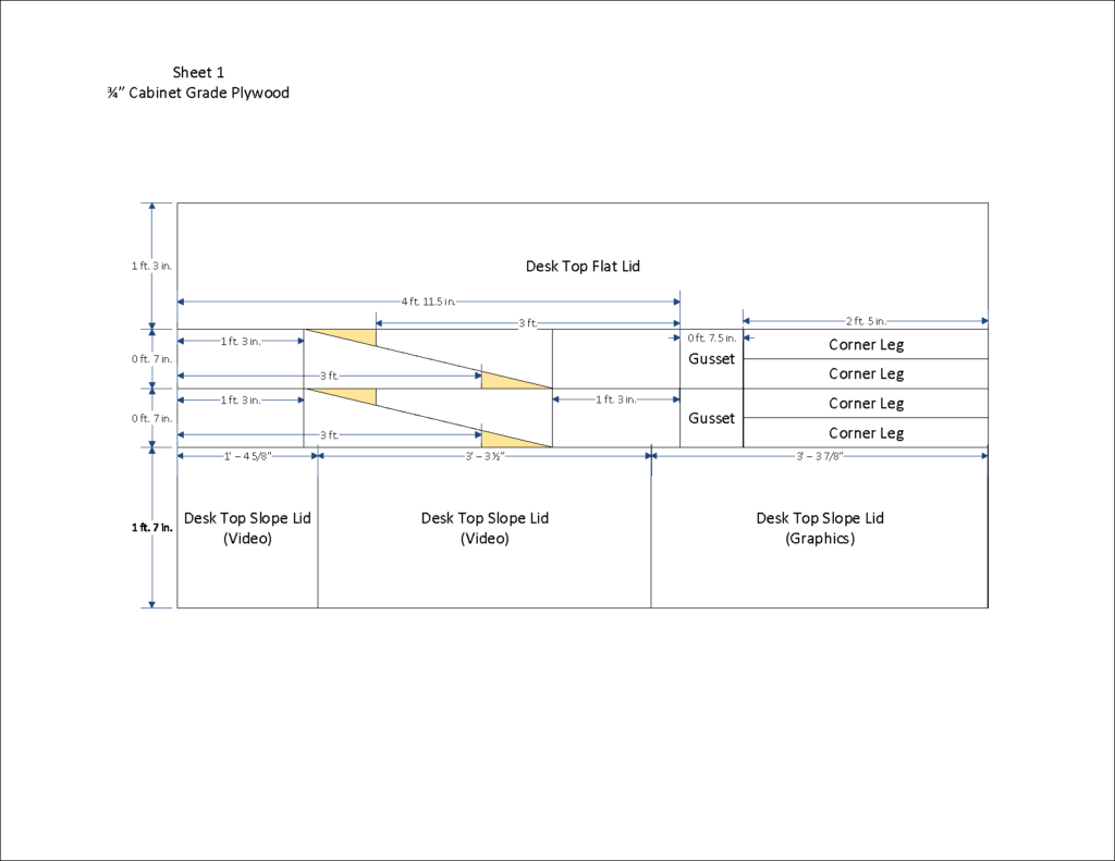
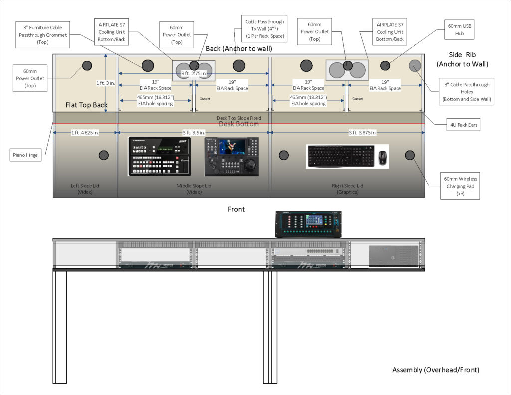
I had about 8 feet of space to work with, and could go about 3 feet deep. After tinkering around in Visio, I was able to come up with a design that could be cut from two sheets of cabinet grade plywood, provide a sloped front, in which the switcher and camera controller could be flush mounted, while also providing four bays with 4U of rack space each, where I could mount things like power strips, network switch, a patch panel, and various other bits.

Cut sheet for the first sheet

Note: the vertical dotted lines on the ribs are NOT CUTS! the lumber yard missed that memo, and I had to work around that.

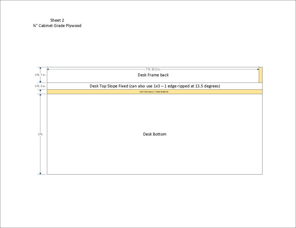
Cuts for the second sheet of plywood

An artifact of this being a two-sheet design means that there’s bar at the top of the sloped face that is fixed in place – That does somewhat impede the access to the top rack space (more on that in a second) – you could use a third sheet and make the movable panels go the whole height.

This is also where I discovered that the “imported birch faced cabinet plywood” that my local lumber yard sells is basically 3/4″ worth of layers of cheap luaun with a birch veneer and a whole lot of glue. I would not recommend this material or use it again. It’s a pain in the ass to saw and sand, and it splinters like crazy. It got the job done, but it’s got some challenges (running a hole saw on this stuff sucks). Well worth spending an extra few bucks on actual hardwood cabinet plywood.

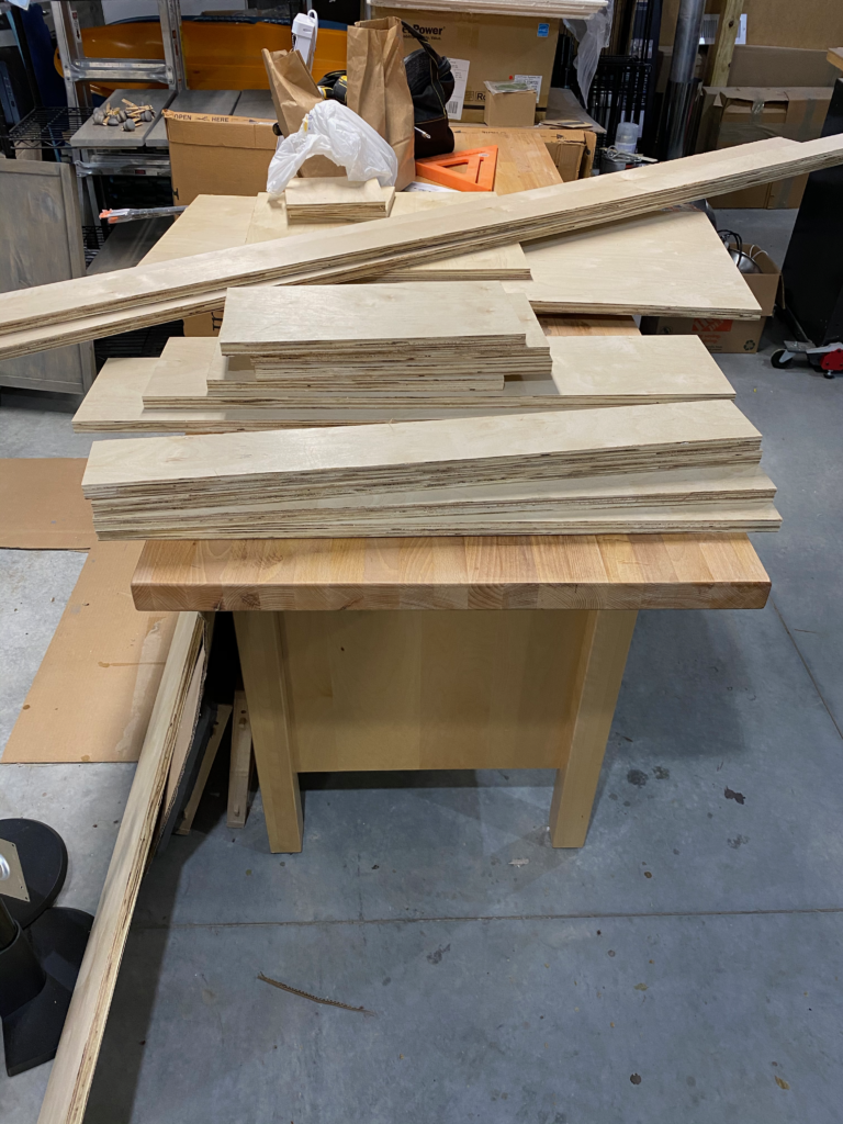
Once I got the big cuts done by the lumber yard, I had another member of the tech team handle the angle cuts with his table saw (where he also noticed that the wood quality was poor), since I lacked that particular bit of equipment.

Pile of boards ready for assembly
Ready to start putting together…

Getting down into the details of the assembly required some planning ahead. I had initially planned for 6″ space inside, until I realized that our current presentation computer is 6.2″ high. Then I remembered that 4U of rack space is 7″, so I altered the design (before cutting!) to create four bays of 4U each, and ordered four sets of rack mounting rails to go in the space.

Working design for the assembly – there are three bays: two with a pair of 19″ rack bays, and one on the end that is a few inches short – Things like power supplies and a Mac Mini live in here. Because of the updated monitor placement, the Qu-PAC ended up inside.

You’ll notice here that I have a bunch of passthru holes and outlet packs on the back deck – those have mostly gone away owing to the TVs and screens taking up the back 5″ or so of the deck. I may still add a few on the back deck between the rack bays. Once I get the hinged lids going, they will contain a wireless charging pad for mobile devices.

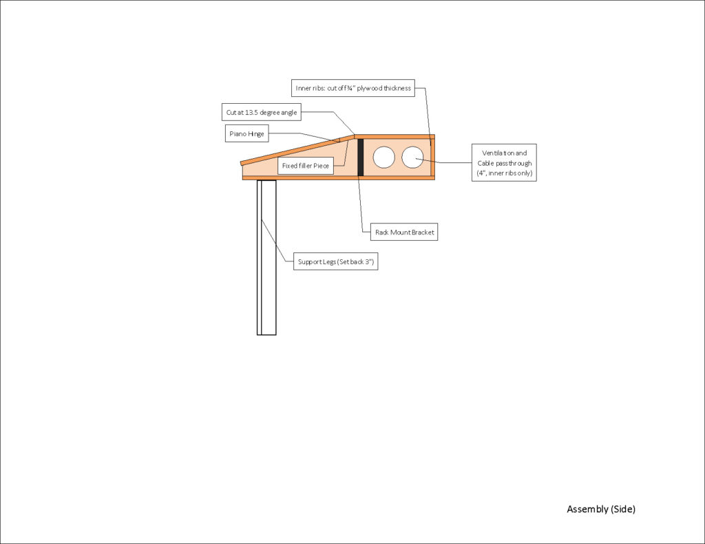
The side view – Holes between the ribs allow for airflow and cable passthrough.
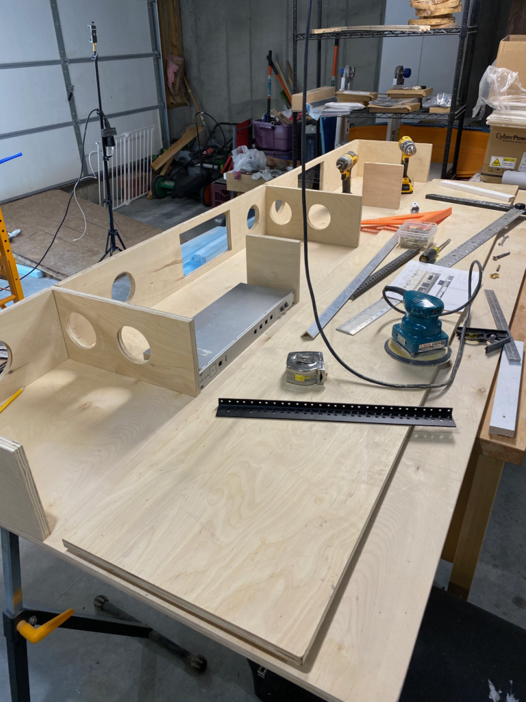
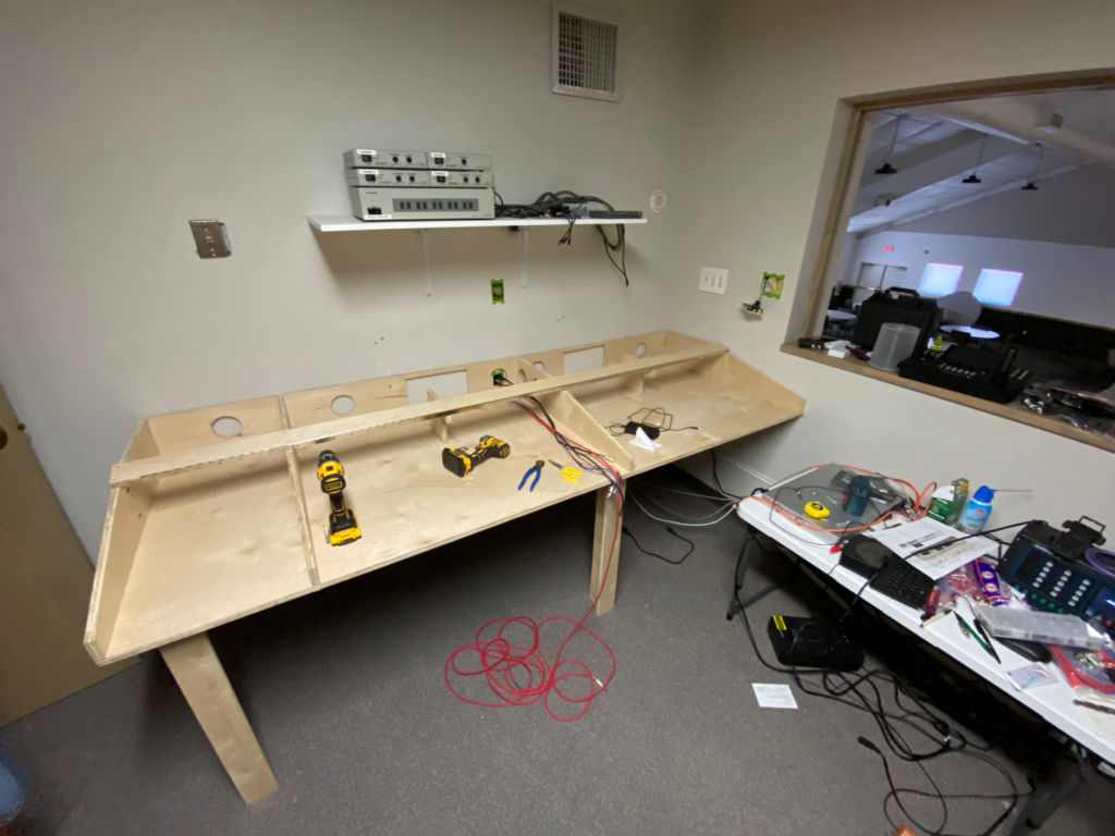
Assembling the unit – using a piece of rack equipment to get the spacing right. Holes in the back are for cable and ventilation. They were carefully placed so as not to encounter a stud when installed.
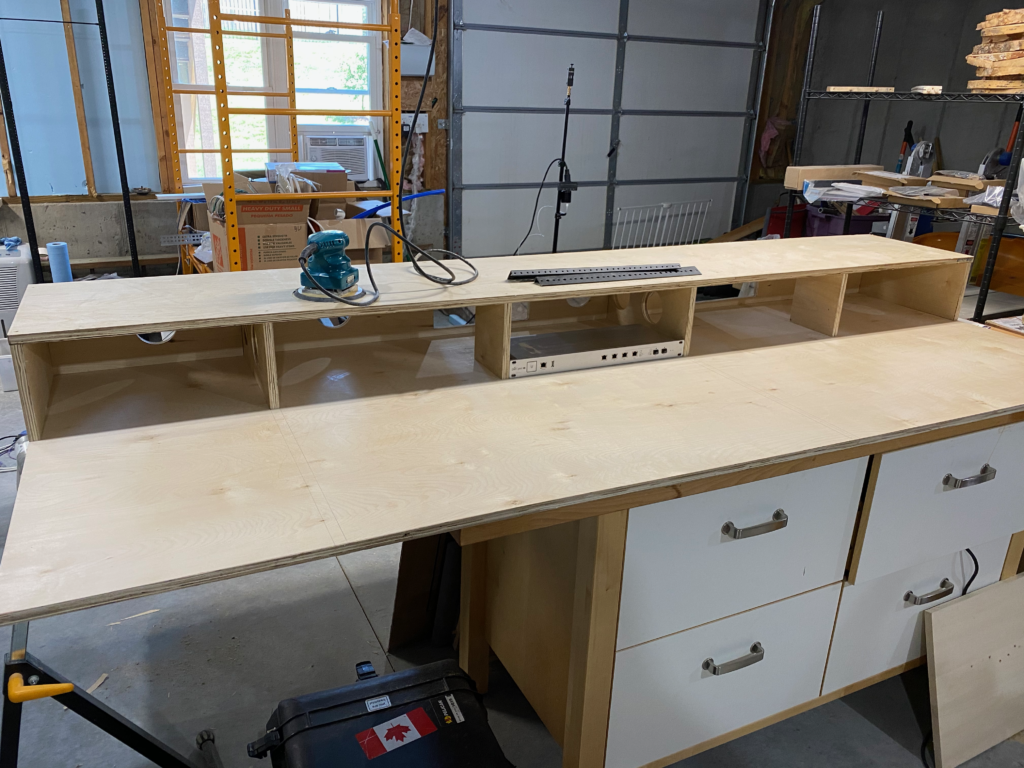
Making some headway.

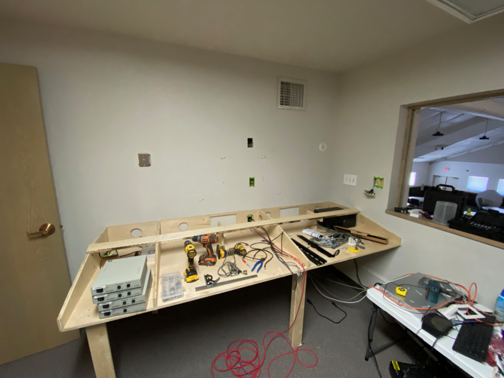
When it came time to haul it over to the church, I removed the top panels just to make it easier to maneuver and carry into the booth.

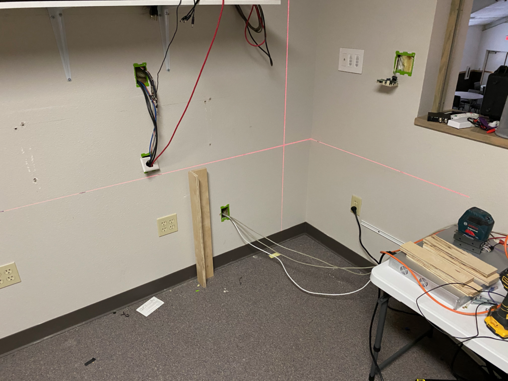
Installation time: A couple of scraps from cutting the ventilation holes were squared off on the radial arm saw and I used them as cleats to support the desk (using a laser to align it with the top of the legs)

We got it within about 1/64″ of level… I’ll take it.
Got it at least somewhat functional for Sunday… We thought we had a few weeks to do this before we re-opened in-person worship, but then our council accelerated the timeline.

I left the front lip open to provide for airflow.

First sunday with the new desk. Lid is off as we figure out best arrangement and connections of the equipment. Once we get that all figured out, we’ll clean it up real nice.

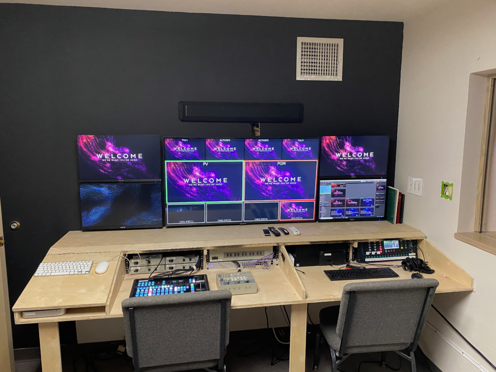
I was able to find a set of matching Asus monitors that were inexpensive and used a VESA mount, and while those were on their way, I painted the wall behind them in flat stage black (makes the displays blend in better, and the wall was in dire need of a coat of paint anyway, so I used some of the paint left over from painting the stage)

Aligning the monitors required a lot of careful planning and the laser level. Here you can see the cable passthroughs and the fan packs.
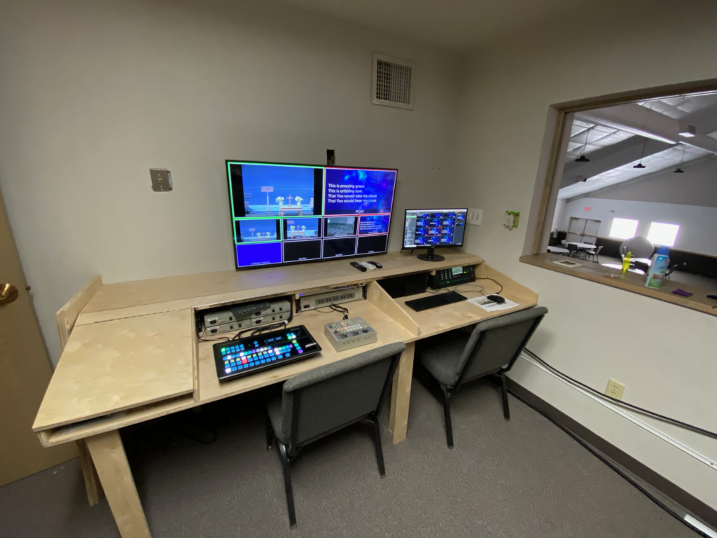
Final layout without the lids – Still not 100% sure they’ll ever make it on… We shall see. Sound bar had to go up high (suboptimal) to keep the displays lower. It works OK for what we need it to though.

Materials List:

  • 2 or 3 sheets of 3/4″ cabinet grade hardwood plywood
  • 2″ finish screws (recommend Torx or Robertson head)
  • 4 sets of 4U rack brackets
  • 2 36″ piano hinges
  • 1 24″ piano hinge (you’ll need to cut this one to length)
  • Any trim or edge veneer you wish – We’re putting a lip on the bottom edge of the lid.
  • 2 AC Infinity AirPlate fan packs – Based on the way I built our desk, I had to flip the fans around to change the flow direction. You can either vent below the cabinet into the existing space, or vent to the rear (in our facility, the wall leads to a big empty ceiling space above the kitchen. These have a manual speed control, but a thermostat control version is also available.

Optional Components:

Tools:

  • Hole saws for the large holes
  • Forstner bits for smaller holes
  • Drill (and small bits for pilot holes)
  • Kreg Jig for pocket screws
  • Belt Sander with coarse belt (for evening things out)
  • Laser level (for installation)
  • Orbital sander with 120/180/220 grit pads (for smoothing things out)
  • Power driver (impact or drill – cordless helps a LOT here)
  • T square/Try square
  • Clamps
  • Table Saw
  • Radial Arm or sliding miter saw
  • Jig saw or reciprocating saw

Tech Equipment:

And that’s the story so far… I’ll update the post as changes warrant.

Hiding In Plain Sight

One of my favorite things to do when I’m at a Disney park is to play the wireless nerd’s version of Hidden Mickeys: Trying to spot the myriad creative ways in which Disney’s Imagineers have blended their excellent wireless network into the carefully contrived scenery. It truly is magical how they can make wireless everywhere while keeping it nearly invisible.

So naturally, when I’m wearing the wireless engineer hat and have a challenge where I get to flex some of that creativity, I’m all over it.

A few years back, I helped a church in Wichita overhaul their aging and underpowered WiFi by designing and installing a new Ruckus system. Last year, they embarked on a new project to add a chapel to their campus. Naturally they wanted to extend the wireless LAN to this new building.

But… It’s a chapel aimed at doing weddings and other sorts of events, so it was paramount that the wireless equipment not be visible, to maintain clean architectural lines with a minimum amount of obvious tech equipment. Some concessions had to be made for audiovisual, but visible access points were a (network) bridge too far.

After pondering the problem as well as observing drawings and renderings, I happened upon the architectural lighting elements in the plan that were mounted on each of the columns. I dug into the design of these and discovered that they were a pair of LED fixtures concealed inside some finish carpentry with a textured plastic surface. And most importantly, there was an empty space in the middle between the two light fixtures that measured about 20cm square by 40cm high, and centered approximately 8 feet off the floor. Not only was that low enough to keep the APs close to the clients, there was plenty of room to put in one of the Ruckus H510 Wall APs designed for the hospitality market (which I also currently have in my house running Unleashed, although they will soon make way for some of the Aruba AP303H units or their new Instant On AP11D counterpart). I’m a big fan of these in-wall units for many reasons.

I asked the electricians to give me a box and conduit to four of these columns, as well as a pair of data cables. I only planned to use two access points initially, but since running cable would be prohibitively difficult after the buildout, I wanted to keep my options open should capacity needs increase in the future.

After many months of construction (Summer of 2019 was an utterly awful weather summer if you were in the construction business), I finally got the green light to install these. I took a bit of personal time on my way down to another job in Oklahoma for my employer, and executed the plan. I’m pretty happy with the results.

The lighting fixture: two pieces of dark wood on either side floating 1″ off the wall with a textured face and tunable color temp LED fixtures facing up and down
The lighting fixture with the plastic face slid up (there’s a stop at the bottom). An electrical box was placed behind it and a 2″ hole drilled for cable access. The overall construction of this fixture is beautifully simple: a few pieces of solid oak and some stain. The overall look in this space is one of stone, wood, and glass, with 90° and 45° angles being dominant.
The Ruckus H510 bracket screwed directly to the finish carpentry. The mount could also have screwed to the electrical box but that was an unnecessary level of effort.
The Ruckus H510 access point mounted on the bracket.
The fixture with the AP mounted inside. The wood and textured face provide minimal attenuation, and in this environment, I’m using the attenuation constructively. The recess in white is where a large TV (in lieu of projection) will be mounted on a swing arm and can fold into the wall when not in use.
Side view – the gap was just enough to get a screwdriver in to secure the AP to the bracket using the provided T10 screws. I was concerned that this wouldn’t be possible.
Lighting fixture side view. Is this with or without the AP installed? If you can’t tell, that means I was successful.
The AP was mounted on the second column from the back of the room, near the sound booth. The corresponding column on the other side is wired for an AP if capacity requires one.
The AP was mounted on the third column from the front of the room, near the front of the stage. The corresponding column on the other side is also wired for an AP if additional client capacity requirements dictate it.
Morning Fog along the Flint Hills National Scenic Byway

Mist Deployment, Part Deux

Second in a series about our first deployment of a Mist Systems wireless network. 

In my last post, I gave you an overview of the various components of the Mist Wireless system. This post will go into some of the design considerations pertaining to this particular project.

Because we’re now designing for more than just Wi-Fi, there are a few additional things to factor in when planning the network.

Floor Plans

It’s not uncommon for your floor plans to have a “Plan North” that doesn’t always line up with “Geographic North”. Usually this isn’t a factor, but looking at it in hindsight, I would strongly encourage you to build your floor plans aimed at geographic north from the start, as the Mist AI will also use that floor plan for direction/wayfinding and the compass in mobile devices will be offset if you just go with straight plan north. You can also design on plan north, but then output a second floor plan file that is oriented to true north. Feature request to Mist: Be able to specify the angle offset of the plan from true north and correct that for user display in the SDK.

For this project, I had access to layered AutoCAD files for the entire facility, which (sort of) makes things easier in Ekahau Site Survey, but sort of doesn’t – the import can get a little overzealous with things like door frames. I had to go do a fair bit of cleanup afterwards, and might have been better off just drawing the walls in the first place. This was partly due to the general lack of any good CAD tools on MacOS that would have allowed me to look at the data in detail and massage it before attempting the import into Ekahau. The other challenge is that ESS imported the ENTIRE sheet as its view window, which made good reporting impossible as the images had wide swaths of white space. Having the ability to crop the CAD file would have been nice.

Density Considerations

View from the rear of the main sanctuary at College Park Church in Indianapolis.

Since one of the areas being covered is a large auditorium, we had to plan on multiple small cells within the space. We needed to put the APs in the catwalks, as we did not have the option of mounting the units on the floor because of the sanctuary being constructed onslab (and while the cloud controller allows you to specify AP height and rotation from plan north, there is no provision to tell it the AP is facing *up* and located on/near the floor). This posed a few challenges, the first being that we were well above the recommended 4-5m (the APs were at 10m from the floor), the other being that we needed to create smaller cells. For this, we used the AP41E with an AccelTex 60-degree patch antenna.

Acceltex 8/10 dBi 60° 4-element patch antenna

 We also needed to either run a whole lot of cables up to the theatrical catwalks, or place a couple of small managed PoE switches – we unsurprisingly opted for the latter, using two 8-port Meraki switches, and uplinked them using the existing data cabling that was feeding the two UniFi APs that were up there.

As an added bonus, the sanctuary area was built with tilt-up precast concrete panels, which allowed us to use that heavy attenuation to our benefit and flood the sanctuary space with APs and not worry about spilling out too much.

Capacity-wise, we used 10 APs in the space, which seats 1700. Over the course of several church designs, I’ve found that a ratio of one active user for every three seats usually works out pretty well – in most church sanctuaries, the space feels packed when 2/3 of the seats are occupied, which means that we’re actually planning for one client for every two seats. Now, we’re talking active clients here, not associated clients. An access point can handle a lot more associations than it can active clients. As a general rule, I try to keep it to about 40 or 50 active clients per AP, before airtime starts becoming a significant factor.

In an environment like this, you want as many client devices in the room to associate to your APs, even if they’re not actively using them – when they’re not associated, they’re sitting out there, banging away with probe requests (especially if you have any hidden SSIDs), chewing up airtime (kind of like that scene from Family Guy where Stewie is hounding Lois just to say “Hi.”). Once they associate, they quiet down a whole bunch.

In addition to the main sanctuary, there are also a couple of other smaller but dense spaces: the chapel (seats 300) and the East Room (large classroom that can seat up to 250). In these areas, design focused on capacity, rather than coverage.

Structural Considerations

As is often the case with church facilities, College Park Church is an amalgamation of several different buildings built over a span of many years, accommodating church growth. What this ends up meaning is that the original building is then surrounded on multiple sides with an addition, and you end up with a lot of exterior walls in the middle of the building, as well as many different types of construction. Some parts of the building were wood-frame, others were steel frame, and others were cast concrete. The initial planning on this building was done without an onsite visit, but the drawings made it pretty obvious where those exterior (brick!) walls were. Naturally, this also makes ancillary tasks like cabling a little interesting.

Fortunately, the church had a display wall that showed the growth of the church which included several construction pictures of the building, which was almost as good as having x-ray vision.

Aesthetic Considerations

Because this is a public space, the visual appearance of the APs is also a key factor – Sometimes putting an AP out of sight takes precendence over placing for optimal Wi-Fi or BLE performance.

Placement Considerations

Coverage Area

Mist specifies that the BLE array can cover about 2500 square feet. The wifi can cover a little more, but it doesn’t hurt to keep your wifi cells that size as well, since you’ll get more capacity out of it. In most public areas of the building, we’re planning for capacity, not coverage. With Mist, if you need to fill some BLE coverage holes where your wifi is sufficient, you can use the BT11 as a Bluetooth-only AP.

AP Height

Mist recommends placing the APs at a height of 4-5m above the floor, in order to provide optimal BLE coverage. The cloud controller has a field in the AP record where you can specify the actual height above the floor.

AP Orientation

Because the BLE array is directional, you can’t just mount the APs facing any direction you please. These APs are really designed to be mounted horizontally, the “front” of the AP should be consistently towards plan north, but the controller does have the ability to specify rotation from plan north in case mounting it that way isn’t practical. The area, orientation and height are critical to accurate calculation of location information.

AP Location

Several of the existing APs in older sections of the building were mounted to hard ceiling areas, and we had to not only reuse the data cable that was there, but also the location. Fortunately, the previous system (Ubiquiti UniFi) was reasonably well-placed to begin with, and we were able to keep good coverage and reuse those locations without any trouble.

There were also some co-existence issues in the sanctuary where we had to make sure we stayed out of the way of theatrical lighting and fixtures that would pose a problem with physical or RF interference. In the sanctuary, we also have to consider the safety factor of the APs and keeping them from falling onto congregants like an Australian Drop-Bear.

Planning for BLE

Since starting this project, I’ve begun working with Ekahau on testing BLE coverage modeling as part of the overall wifi coverage, and it’s looking very promising. I was able to go back to the CPC design and replan it with BLE radios, and it’s awesome. Those guys in Helsinki keep coming up with great ideas. As far as Ekahau is concerned, multi-radio APs are nothing too difficult – They’ve been doing this for Xirrus arrays for some time now, as well as the newer dual-5GHz APs.

Stay tuned for a post about BLE in Ekahau when Jussi says I’m allowed to talk about it.

Up Next: The Installation


Cover Image: Explore Kansas: The Flint Hills National Scenic Byway (Kansas Highway 177)

Misty valley landscape with a tree on an island

Mist Deployment (Part The First)

First in a series about our first deployment of a Mist Systems wireless network. Mist Systems Logo

Over the course of the past few months, I’ve been working with the IT staff at College Park Church in Indianapolis to overhaul their aging Ubiquiti UniFi wireless system. They initially were looking at a Ruckus system, owing to its widespread use among other churches involved with the Church IT Network and its national conference (where I gave a presentation on Wi-Fi last fall). We had recently signed on as a partner with industry newcomer Mist Systems, and had prepared a few designs of similar size and scope for other churches in the Indianapolis area using the Mist system. We proposed a design with Ruckus, and another with Mist, with the church selecting Mist for its magic sauce, which is its Bluetooth Low Energy (BLE) capability for location engagement and analytics.

Fundamentally, the AP count, coverage, and capacity were not significantly different with Ruckus vs. Mist, and Mist offered a few advantages over the Ruckus in terms of the ability to add external antennas for creating smaller cells in the sanctuary from the APs mounted on the catwalks, as floor mounting was not an option.

About Mist

Mist is a young company that’s been around for about two or three years, and they have developed a couple of cool things in their platform – The first is what they call their AI cloud, the second is their BLE subsystem, and the last is their API.

Their AI component is a cloud management dashboard (similar to what you would see with Ruckus Cloud or Meraki — many of the engineers that started with Mist came over from Meraki), where the APs are constantly analyzing AP and client performance through frame capture and analysis, and reporting it back to the cloud controller. The philosophy here is that a large majority of the issues that users have with Wi-Fi performance is actually related to performance on the wired side of the network (“It’s always DNS.” Not always, but DNS — and DHCP — are major sources of Wi-Fi pain). The machine learning AI backend is looking at the stream of frames to detect problems, and then using that to generate Wi-Fi SLA metrics that can help determine where problems lie within the infrastructure, and doing some analysis of root causes. An example of this is monitoring the entire Station/AP conversation during and shortly following the association process. It looks at how long association took. How long DHCP took (and if it was successful), whether 4-way handshakes completed, and so on. It will also keep a frame capture of that conversation for further manual troubleshooting. It also keeps a log of AP-level events such as reboots and code changes so that client errors can be correlated on a timeline to those events. There’s a lot more it can do, and I’m just giving a brief summary here. Mist has lots of informational material on their website (and admittedly, there’s a goodly amount of marketing fluff in it, but that’s what you’d expect on the vendor website).

Graphs of connection metrics from the Mist system


Next, we have their BLE array. This is what really sets Mist apart from the others, and is one of the more interesting pieces of tech to show up in wifi hardware since Ruckus came on the scene with their adaptive antenna technology. Each AP has not one, but *eight* BLE radios in it, coupled with a 16-element antenna array (8 TX, 8RX). Each antenna provides an approximately 45° beam covering a full circle. Mist is able to use this in two key ways. One is the ability to get ridiculously precise BLE location information from their mobile SDK, (and by extension, locate a BLE transponder for asset visibility/tracking) and the other is the ability to use multiple APs to place a virtual BLE beacon anywhere you want without having to go physically install a battery-powered beacon. There are myriad uses for this in retail environments, and the possibilities for engagement and asset tracking are very interesting in the church world as well.

Lastly, we have their API. According to Mist, their cloud controller’s web UI only exposes about 40% of what their system can do. The remainder is available via a REST API that will allow you do do all kinds of neat tricks with it. I haven’t had a chance to dig into this much yet, but there’s a tremendous amount of potential there. Jake Snyder has taught a 3-day boot camp on using Python in network administration to leverage the power of APIs like the one from Mist (Ruckus also has an API on their Cloud and SmartZone controllers)

Mist is also updating their feature set on a weekly basis – rather than one big update every 6 months that may or may not break stuff, small weekly releases allow them to deploy features in a more controlled manner, making it easy to track down any potential show-stopper bugs, preferably before they get released into the wild. You can select whether your APs get the early-release updates, or use a more extensively tested stable channel.

Much like Meraki, having all your AP data in the cloud is tremendously useful when contacting support, as they have access to your controller data without you having to ship it to them. They can also take database snapshots and develop/test new features based on real data from the field rather than simulated data. No actual upper-layer traffic is captured.

The Hardware

note: all prices are US list – specific pricing will be up to your partner and geography.

There are four APs in the Mist line. The flagship 4×4 AP41 ($1385), the lower-end AP21 ($845), the outdoor AP61 ($?) , and the BLE-only BT11 ($?). The AP41 also comes in a connectorized version called the AP41E, at the same price as the AP41 with the internal antenna.

The AP41/41E is built on a cast aluminum heat sink, making the AP noticeably heavy. It offers an Ethernet output port, a USB port, a console port, and what they call an “IoT port” that provides for some analog sensor inputs, Arduino-style. It requires 802.3at (PoE+) power, or can use an external 12V supply with a standard 5.5×2.5mm coaxial connector. In addition to the 4-chain Wifi radio and the BLE array, the AP41 also has a scanning radio for reading the RF environment. On the AP41E, the antenna connectors are located on the downward face of the AP.

The AP21 is an all-plastic unit that uses the same mounting spacing as the AP41, and has an Ethernet pass-through port with PoE (presumably to power downstream BT11 units or cameras). Like the AP41, it also has the external 12V supply option.

This install didn’t make use of BT11 or AP61 units, so I don’t have much hands-on info about them.

It’s also important to note that none of these APs ship with a mounting bracket, nor does the AP have any kind of integrated mounting like you would find on a Ruckus AP. Mist currently offers 3 mounting brackets: a T-Rail bracket ($25), a drywall bracket ($25) and a threaded rod bracket ($40). The AP attaches to these brackets via four T10 metric shoulder screws (Drywall, Rod), or four metric Phillips screws (T-Rail). More on these later.

The Software

Each AP must be licensed, and there are three possibilities: Wifi-only, BLE Engagement, and BLE Asset tracking. Each subscription is nominally $150/year per AP, although there are bundles available with either two services or all three. Again, your pricing will depend on your location and your specific partner. Mist recently did away with multi-year pricing, so there’s no longer a cost advantage in pre-buying multiple years of subscriptions.

When the subscription expires, Mist won’t shut off the AP the way Meraki does, however, the APs will no longer have warranty coverage. After a subscription has been expired for two months, Mist will not reactivate an AP. The APs will continue to operate with their last configuration, however, but there will no longer be access to the cloud dashboard for that AP.

Links:

Mist Systems

Jake Snyder on Clear To Send podcast #114: Automate or Die

Mist Product Information

Up Next: The Design

Using Bitmovin Player with Church Online Platform

Today’s post will be a brief tutorial on using Bitmovin‘s excellent HTML5 video player with Church Online Platform.

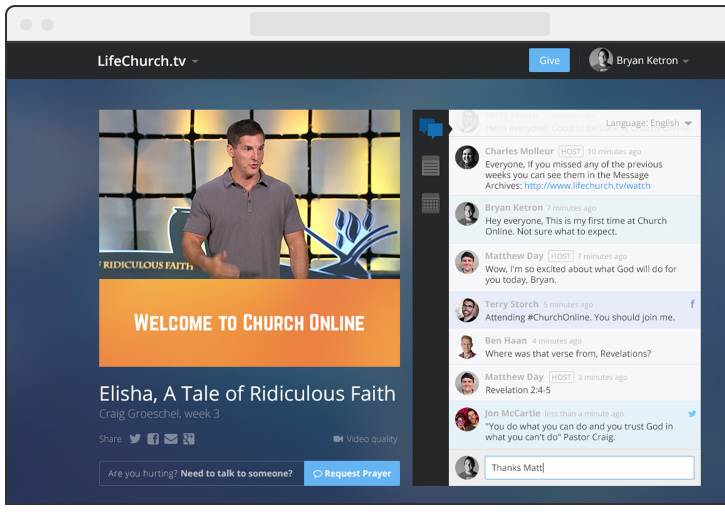
If you’re a church that is wanting to go live, and you haven’t discovered COP, it’s a marvelous product. The fine folks on the life.church Digerati Team (who created the Bible App and made it available on just about every platform known to mankind). It’s a free hosted platform that lets you deliver church online. All you have to do is bring your own streaming provider and provide an embed code. You can use your provider’s player, or you can use your own player. The Digerati team are also a client of mine, and I really enjoy working with them – they’re talented, nerdy, and very good at what they do. (most recently, I helped them build out their Wowza Streaming Engine capability for automating the scheduling and delivery of simulated live events.)

One of my favorite video players out there right now is from Bitmovin, and they provide a CDN-hosted player that provides excellent analytics (complete with API access for the especially nerdy), and usage is free for the first 5000 impressions (and pricing is quite reasonable as you scale up from there). For this reason alone, it’s an excellent choice for churches getting started with streaming. Its other major benefit is that because it is written in HTML5 and Javascript, it will work on just about anything you can throw at it (for the really archaic devices, it still has a Flash component). It also is designed from the ground up to support the new MPEG-DASH standard, but if you’re using a streaming CDN or service that doesn’t provide DASH, no big deal, as the player also supports HLS, even for Flash delivery for those 3 devices that still haven’t discovered modern streaming technology or are running a particularly ancient version of Android. Added bonus, BitMovin’s player also supports VR and 360 streaming (as does Wowza Streaming Cloud).

For starters, you’ll need to sign up for an account, which will give you player information. One thing you’ll want to make sure you do is add your churchonline.org domain to the allowed domains for your license key. This is under Player/Overview:

Bitmovin Player Domain Config

If you forget to do this, the player will simply show an error telling you you need to do it.  This keeps someone from using your player key on their site, so be sure to use yourdomain.churchonline.org, not just churchonline.org.

To put this in your COP page, go to the event where you wish to use the player, and go to the Video tab:

ChurchOnline Event Settings

When you go to the Embed menu, you will see code to put it on the page (under Default video embed code). This is a little more involved than your standard embed code.

Bitmovin Embed Controls

A couple of key things to note here with regards to COP:

  1. In order to put the <script> stuff in your <head> section, you’d need to create a custom theme in COP. This is not necessary (in fact, putting that script statement in the head that way doesn’t work). What you’ll need to do is simply put the <script> piece just above the rest of it in the default embed code section.
  2. You’ll need to edit the source section in that code. If all you’re doing is HLS, you can remove the dash and progressive entries. Leave the HLS entry in place and put in the HLS URL provided by your streaming platform. In the case of Wowza Streaming Cloud, this is located at the bottom of the Overview tab of your streaming application under “Playback URLs”.
  3. The “poster” entry is the image the player shows when you’re not streaming any video.

So, for my test stream, the embed code looks like this:


<script type="text/javascript" src="https://bitmovin-a.akamaihd.net/bitmovin-player/stable/7/bitmovinplayer.js"></script>

<div id="player"></div>
<script type="text/javascript">
var conf = {
key: "d8XXXXXX-XXXX-XXXX-XXXX-XXXXXXXXXX2e",
source: {
hls: "http://wowzaprod103-i.akamaihd.net/hls/live/######/########/playlist.m3u8",
poster: "http://dontfenceme.in/wp-content/uploads/2013/09/g-global-background.jpg"
}
};
var player = bitmovin.player("player");
player.setup(conf).then(function(value) {
// Success
console.log("Successfully created bitmovin player instance");
}, function(reason) {
// Error!
console.log("Error while creating bitmovin player instance");
});
</script>

The console.log lines aren’t necessary, but potentially useful when trying to debug why it can’t instantiate the player.

If you want to run a separate video when the doors aren’t open, put that under the offline video embed code section. You can leave the mobile and low sections empty, as your stream is probably already adaptive from your streaming provider.

Save it, and this is what you get:

BitMovin in ChurchOnline Platform

In order to remove the Bitmovin logo, edit the theme’s CSS and add the following lines:


/* Remove Bitmovin Logo on player */
.bmpui-ui-watermark {
display: none;
}

ChurchOnline Platform CSS Edit

Enhancing the public Wi-Fi experience

Recently, there was an excellent blog post from WLAN Pros about “Rules for successful hotel wi-fi“. While it is aimed primarily at Wi-Fi in the hotel business (where there is an overabundance of Bad-Fi), many of the tips presented also apply to a wide variety of large-scale public venue wifi installations. Lots of great information in the post, and well worth a read.

At the 2016 WLPC there was an interesting TENTalk from Mike Liebovitz at Extreme Networks about the pop-up wifi at Super Bowl City in San Francisco, where analytics pointed to a significant portion of the traffic being headed to Apple.

Meanwhile, a few months later at the 2016 National Church IT Network conference, I heard a TENTalk about Apple’s MacOS Server, where I first heard about this incredibly useful feature (sadly, it wasn’t recorded, that I know of, so I can’t give credit…)

With most of the LPV installations I’ve worked on, I’ve found the typical client mix includes about 60% Apple devices (mostly iOS). For example, this is at a large church whose wireless network I installed. (Note that Windows machines make up less than 10% of the client mix on wifi!)

Client mix from Ruckus ZoneDirector

OK, So what?

This provides an opportunity to make the wifi experience even better for your (Apple-toting) guests. Whenever possible, as part of the “WiFi System” I will install an Apple Mac Mini loaded with MacOS Server. This allows me to turn on caching. This is not just plain old web caching like you would get with a proxy server such as Squid, but rather a cache for all things Apple. What does this do for your fruited guests? It speeds up the download of software distributed by Apple through the Internet. It caches all software and app updates, App Store purchases, iBook downloads, iTunes U downloads (apps and books purchases only), and Internet Recovery software that local Mac and iOS devices download.

Why is this of interest and importance? Let me give you an example: A few years ago, we were hosting a national Church IT Round Table conference at Resurrection on a day when Apple released major updates to MacOS, iOS, and their iWork suite. In addition to the 50 or so staff Mac machines on the network, there were another hundred or two Mac laptops and iThings among the conference attendees. The 200MB internet pipe melted almost instantly under the load of 250 devices each requesting 3-5GB of updates. That would have melted even a gigabit pipe, and probably given a 10Gbps pipe a solid run for its money (not to mention bogging down some of the uplinks on the internal network!. Having a caching server would have mitigated this. It didn’t do great things to the access points in the conference venue either, all of which were not only struggling for airtime, but also for backhaul.

Just by way of an example, Facebook updates their app every two weeks and its current incarnation (86.0, March 30, 2017) weighs in at 320MB (the previous one was about half that!), and its close pal Messenger clocked in at 261MB. Almost everyone has those to apps, so they’re going to find itself in your cache almost instantly, along with numerous other popular apps. Apple’s iWork suite apps and Microsoft Office apps all weigh in around 300-500MB apiece as well. This has potential to murder your network when you least expect it. (A few years back, the church where I was working hosted the national Church IT conference that happened to coincide with Apple’s release of OSX Mavericks, and a major iWork update for both iOS and MacOS. The conference Wi-Fi and the church’s 200Mbps WAN pipe melted under the onslaught of a couple hundred Apple devices belonging to the guest nerds and media staff dutifully downloading the updates.)

In any case, check out the network usage analytics from either your wireless controller or your firewall. If Apple.com is anywhere near the top of the list (or on it at all), you owe it to yourself and your guests to implement this type of solution.Network Statistics from Ubiquiti UniFi

The Technical Mumbo-Jumbo

Hardware

As mentioned previously, a Mac Mini will do the job nicely. If you’re looking to do this on the cheap, it will happily run on a 2011-vintage Mini (you can find used Mac Minis on Craigslist or eBay all day long for cheap), just make sure you add some extra RAM and a storage drive that doesn’t suck (the stock 5400rpm spinning disks on the pre-2012 era Mac Mini and iMacs were terrible.) Fortunately, 2.5″ SSDs are pretty cheap these days. Newer Minis will have SSD baked in already.

If you’re wanting to put the Mac Mini in the datacenter, you might want to consider using a Sonnet RackMac Mini (which is available on Amazon for about $139) and can hold one or two machines.

Sonnet RackMac Mini

You can also happily run this off of one of the 2008-era “cheese grater” Mac Pros that has beefier processing and storage (and also fits in a rack, albeit not in the svelte 1U space the Sonnet box uses). If you have money to burn, then by all means use the “trash can” Mac Pro (Sonnet also makes a rack chassis for that model!).

This is a great opportunity to re-purpose some of those Macs sitting on the shelf after your users have upgraded to something faster and shinier.

Naturally, if you’re running a REALLY big guest network, you’ll want to look at something beefy, or a small farm of them Minis with SSD storage (the MacOS Server caching system makes it quite easy to deploy multiple machines to support the caching.)

The Software

MacOS Server (Mac App Store, $19.99)

Since most of your iOS guests will have updates turned on, one of the first things an iOS device does when it sees a big fat internet pipe that isn’t from a cell tower is check for app updates. If you have lots of guests, you will need to fortify your network against the onslaught of app update requests that will inevitably hit whenever you have lots of guests in the building.

The way it works is this: When an Apple device makes a request to the CDN, Apple looks at the IP you’re coming from and says, “You have a local server on your LAN, get your content from there, here’s its IP.” The result being that your Apple users will get their updates and whatnot at LAN speeds without thrashing your WAN pipe every time anyone pushes out a fat update to an app or the OS, which is then consumed by several hundred people using your guest wifi over the course of a week. You’ve effectively just added an edge node to Apple’s CDN within your network.

Content will get cached the first time a client requests it, and it does not need to completely download to the cache before starting to send it to the client. For that first request, it will perform just as if they were downloading it directly from Apple’s servers. If your server starts running low on disk space, the cache server will purge older content that hasn’t been used recently in order to maintain at least 25GB of free disk space.

MacOS Caching Server Configuration

The configuration

If you have multiple subnets and multiple external IPs that you want to do this for, you can either do multiple caching servers (they can share cache between them), or you can configure the Mini to listen on multiple VLANs:

Mac OS network preferences panel

Once you have the machine listening on multiple VLANs, you can tell the caching server which ones to pay attention to, and which public IPs. The Mac itself only needs Internet access from one of those subnets.

MacOS Server Caching Preferences

The first dropdown will give you the option of “All Networks”, “Only Local Subnets”, and “Only Some Networks”. Choosing the last one opens an additional properties box that allows you to define those networks:

Mac OS Server Cache Network Settings

The second one gives you the options of “Matching this server’s network” or “On other networks”. As with the first options, an additional properties box is displayed.

In both cases, hit the plus sign to create a network object:

Mac OS Server Create a New Network

It should be noted here that this only tells the server about existing networks, but it won’t actually create them on the network interface. You’ll still need to do that through the system network preferences mentioned previously. If you don’t want to have the server listen on multiple VLANs, you can just make sure its address is routable from the subnets you wish to have the cache server available, define the external and internal networks it provides service to, and you should be off to the races. This will provide caching for subnet A that NATs to the internet via public IP A, and B to B, and so on. Defining a range of external IPs also has you covered if you use NAT pooling.

There’s also some DNS SRV trickery that may need to happen depending on your environment. There are some additional caveats if your DNS servers are Active Directory read-only domain controllers. This post elaborates on it.


Is it working?

Click the stats link near the top left of the server management window. At the bottom is a dropdown where you can see your cache stats. The red bar shows bytes served from the origin, and green shows from the cache. If you only have one server doing this, you won’t see any blue bars, which are for cache from peer servers. Downside is that you can only go back 7 days.

On this graph, 3/28 was when there were both a major MacOS and iOS update released, hence the huge spike from the origin servers on Apple’s CDN. Nobody has updated from the network yet… But guest traffic at this site is pretty light during the week. I’ll update the image early next week.

MacOS Server Cache Stats

Other useful features

A side benefit of this is that you can also use this to provide a network recovery boot image on the network, in case someone’s OS install ate itself – on the newer Macs with no optical drive, this boots a recovery image from the internet by default. This requires some additional configuration, and the instructions to set up NetInstall are readily available with a quick Google search.

If you want, you can also make this machine the DHCP and local DNS server for your guest network. With some third-party applications, you can also serve up AirPrint to your wireless guests if they need it.

Conclusion

From a guest experience perspective, your guests see their updates downloading really fast and think your WiFi is awesome, and it’s shockingly easy to set up (the longest and most difficult part is probably the actual acquisition of the Mac Mini) It will even cache iCloud data (and encrypts it in the cache storage so nobody’s data is exposed). Even if you have a fat internet pipe, you should really consider doing this, as the transfers at LAN speed will reduce the amount of airtime consumed on the wireless and the overall load on your wireless network. (Side note, if you’re a Wireless ISP, this sort of setup is just the sort of thing you ought to put between your customer edge network and your IP transit)

Of course, you could also firewall off Apple iCloud and Updates instead, but why would you do that to your guests? Are you punishing them for something?

Android/Windows users: So sad, Google and Microsoft don’t give you this option (Although Microsoft sort of does in a corporate environment with WSUS, but it’s not nearly as easy to pull off, nor is it set up for casual and transient users). I would love it if Google would set up something like this for play store, Chromebook, etc, as about half of the client mix that isn’t from Apple is running on Android. You can sort of do it by installing a transparent proxy like squid.

Now, if only we could do the same for Netflix’s CDN. The bandwidth savings would be immense.

Update

(Added November 16, 2017)

As of the release of MacOS High Sierra and MacOS Server 5.4 (release notes), the caching service is now integrated into the core of MacOS, so any Mac on the network can do it, without even needing to install Server. The new settings are under System Preferences > Sharing:


Going Serverless: Office 365

Recently I just completed a project for a small church in Kansas. Several months ago, the senior pastor asked me for a quote on a Windows server to provide authentication as well as file and print share services. During the conversation, a few things became clear:

  1. Their desktop infrastructure was completely on Windows 10. Files were being kept locally or in a shared OneDrive account.
  2. The budget they had for this project was not going to allow for a proper server infrastructure with data protection, etc.
  3. This church already uses a web-based Church Management System, so they’re somewhat used to “the cloud” already as part of their workflows.

One of the key features provided by Windows 10 was the ability to use Office 365 as a login to your desktop (Windows 8 allowed it against a Microsoft Live account). Another is that for churches and other nonprofits, Office 365 is free of charge for the E2 plan.

I set about seeing how we could go completely serverless and provide access not only to the staff for shared documents, but also give access to key volunteer teams and church committees.

The first step was to make sure everybody was on Windows 10 Pro (we found a couple of machines running Windows 10 Home). Tech Soup gave us inexpensive access to licenses to get everyone up to Pro.

Then we needed to make sure the internet connection and internal networking at the site was sufficient to take their data to the cloud. We bumped up the internet speed and overhauled the internal network, replacing a couple of consumer-grade unmanaged switches and access points with a Ubiquiti UniFi solution for the firewall/router, network switch, and access points. This allows me and key church staff to remotely manage the network, as the UniFi controller operated on an Amazon Web Services EC2 instance (t2.micro). This new network also gave the church the ability to offer guest wifi access without compromising their office systems.

The next step was to join everyone to the Azure domain provided by Office 365. At this point, all e-mail was still on Google Apps, until we made the cutover.

Once we had login authentication in place, I set about building the file sharing infrastructure. OneDrive seemed to be the obvious solution, as they were already using a shared OneDrive For Business account.

One of OneDrive’s biggest challenges is that, like FedEx, it is actually several different products trying to behave as a single, seamless product. At this, OneDrive still misses the mark. The OneDrive brand consists of the following:

  • OneDrive Personal
  • OneDrive for Business
  • OneDrive for Business in Office 365 (a product formerly known as Groove)
  • Sharepoint Online

All the OneDrive for Business stuff is Sharepoint/Groove under the hood. If you’re not on Office 2016, you’ll want to make the upgrade, because getting the right ODB client in previous versions of Office is a nightmare. Once you get it sorted, it generally works. If you’ve got to pay full price for O365, I would recommend DropBox for Business as an alternative. But it’s hard to beat the price of Office 365 when you’re a small business.

It is very important to understand some of the limitations of OneDrive for Business versus other products like DropBox for Business. Your “personal” OneDrive for Business files can be shared with others by sending them a link, and they can download the file, but you can’t give other users permission to modify them and collaborate on a document. For this, you need to go back to the concept of shared folders, and ODB just doesn’t do this. This is where Sharepoint Online comes in to play.

Naturally, this being Sharepoint, it’s not the easiest thing in the world to set up. It’s powerful once you get it going, but I wasn’t able to simply drop all the shared files into a Sharepoint document library — There’s a 5000-file limit imposed by the software. Because the church’s shared files included a photo archive, there were WAY more than 5000 files in it.

Sharepoint is very picky about getting the right information architecture (IA) set up to begin with. Some things you can’t change after the fact, if you decide you got them wrong. Careful planning is a must.

What I ended up doing for this church is creating a single site collection for the whole organization, and several sites within that collection for each ministry/volunteer team. Each site in Sharepoint has 3 main security groups for objects within a site collection:

  • Visitors (Read-Only)
  • Members (Read/Write)
  • Owners (Read/Write/Admin)

In Office 365, much as it is with on-premises, you’re much better off creating your security groups outside of Sharepoint and then adding those groups to the security groups that are created within Sharepoint. So in this case, I created a “Worship Production” team, added the team members to the group, and then added that group to the Worship Site Owners group in Sharepoint. The Staff group was added to all the Owners groups, and the visitors group was left empty in most cases. This makes group membership administration substantially easier for the on-site admin who will be handling user accounts most of the time. It’s tedious to set up, but once it’s going, it’s smooth sailing.

Once the security permissions were set up for the various team sites, I went into the existing flat document repository and began moving files to the Sharepoint document libraries. The easiest way to do this is to go to the library in Sharepoint, and click the “Sync” button, which then syncs them to a local folder on the computer, much like OneDrive (although it’s listed as Sharepoint). There is no limit to how many folders you can sync to the local machine (well, there probably is, but for all practical purposes, there isn’t). From there it’s a matter of drag and drop. For the photos repository, I created a separate document library in the main site, and told Sharepoint it was a photo library. This gives the user some basic Digital Asset Management capabilities such as adding tags and other metadata to each picture in the library.

So far, it’s going well, and the staff enjoys having access to their Sharepoint libraries as well as Microsoft Office on their mobile devices (iOS and Android). Being able to work from anywhere also gives this church some easy business continuity should a disaster befall the facility — all they have to do is relocate to the local café that has net access, and they can continue their ministry work. Their data has now been decoupled from their facility. I have encountered dozens of churches over the years whose idea of data backup is either “what backup?” or a hard drive sitting next to the computer 24×7, which is of no use if the building burns to the ground or is spontaneously relocated to adjacent counties by a tornado. The staff doesn’t have to worry about the intricacies of running Exchange or Sharepoint on Windows Small Business Server/Essentials. Everything is a web-based administrative panel, and support from Microsoft is excellent in case there’s trouble.

If you’re interested in how to take your church or small business serverless, contact me and I’ll come up with a custom solution.

Controlling Audio With ProPresenter

Our church is a small one. So its not always especially easy to fully staff our tech booth, and sometimes, one must fly solo, which adds to the workload, and sometimes stuff gets forgotten, like unmuting microphones for the choir or the person reading the scripture.

Fortunately, there is some tech than can help us in this regard. We use ProPresenter for our graphics presentation, and an Allen & Heath QU-24 console for our audio. The Qu-24 is connected to the Mac that runs ProPresenter via a USB cable, which shows up in the Mac as a 32 in/32 out audio device, as well as a MIDI device. This is primarily to be able to use the console as a multitrack and DAW interface, but it also lets us play back audio from ProPresenter media cues without ever leaving the digital domain, and saving us a couple of inputs on the board (although there’s no shortage of those). But because it’s also a MIDI device, this gives us some options with ProPresenter’s $99 MIDI module add-on. The Qu series boards can also do MIDI over IP (in fact, the Qu-Pad remote control app for iPad uses MIDI over IP to work its magic). If you’re using MIDI over IP with a Mac, you’ll need a special driver for the Mac. No driver is needed for USB.

First, a few resources we’ll need:

In the Qu Series, mutes and mute groups are controlled by a sequence of a Note On/Off message. The specific note determines the channel or mute group being controlled, and a the velocity value determines if it’s being turned on (Muted) or off (Unmuted). Velocity values below 64 turn the mute off, and above turn it on.

Meanwhile, over in ProPresenter, since Version 6, we have the ability to add MIDI Note On/Off cues to a slide. See where this is going? Unfortunately, ProPresenter doesn’t have the ability to do anything other than MIDI notes in a slide at the moment, so we can’t get really crazy with starting recordings or anything else requiring non-note MIDI messages.

So how do we know what notes emulate button presses? The documentation provides this handy method:

OK, this requires thinking and math. Not so helpful. This is where the MIDI monitor comes in. Download it and run it, and it shows everything coming across the MIDI interface. Push the button you’re interested in, and lo, MIDI Monitor helpfully shows you what note you’re interested in:

In this case, G#4 is the mute group for our choir. A4 is the mute group for the speaking mics on the chancel. A1 is the lectern mic.

Screenshot 2016-11-20 13.51.30So now, to be able to add a cue at the beginning of a song the choir is singing, I simply have to add two cues to the first slide to turn on the choir microphones:

  • NOTE ON, G#4(80), 63
  • NOTE OFF, G#4(80)

Then I can add a slide at the end of the playlist entry that then turns them back off, or add these to the beginning of the next playlist entry:

  • NOTE ON, G#4(80), 127
  • NOTE OFF, G#4(80)

Likewise, when someone is at the lectern reading scripture, I can unmute that channel automatically using the corresponding note number, and mute them again when they’re done.

On the flip side, you can also use note on/off commands to control ProPresenter. So you *could* also use the Mute, SEL, and PAFL buttons on unused channels to trigger things in ProPresenter (you also want to make sure that you don’t overlap these with the mutes and mute groups that you are actively using so as not to inadvertently advance a slide when hurriedly muting a channel). ProPresenter also conveniently tells you what the last note sent was, so you can actively push the button you want to use, make a note of its number, and put it in the action you wish.


Another approach you can take is to create a presentation in ProPresenter containing blank slides with the various functions you wish to use. Then you can copy these slides into presentations and add a Go To Next timer to them to automatically advance to the next slide. I would also recommend using slide labels and colors to clearly identify what each slide is doing:

Screenshot 2016-11-20 13.47.55


If you have controllable lighting and your lighting console also has MIDI capability, This comes in handy as well. And if you’re really a one-man band, and like to do things like pads underneath certain worship elements, you can use this to trigger those as well. But if you get to that point, you may want to look into QLab to control all of them at the same time.

So there you have it: a quick and easy way to automate some of your workload with the Qu series boards. If you’ve got another board that you use, let me know in the comments if you do (or would like to do) something like this. Would also love to hear if anyone is using hardware MIDI controllers like the Novation LaunchPad and how you have it set up.

Additional Info:

Summary of MIDI Messages (midi.org)