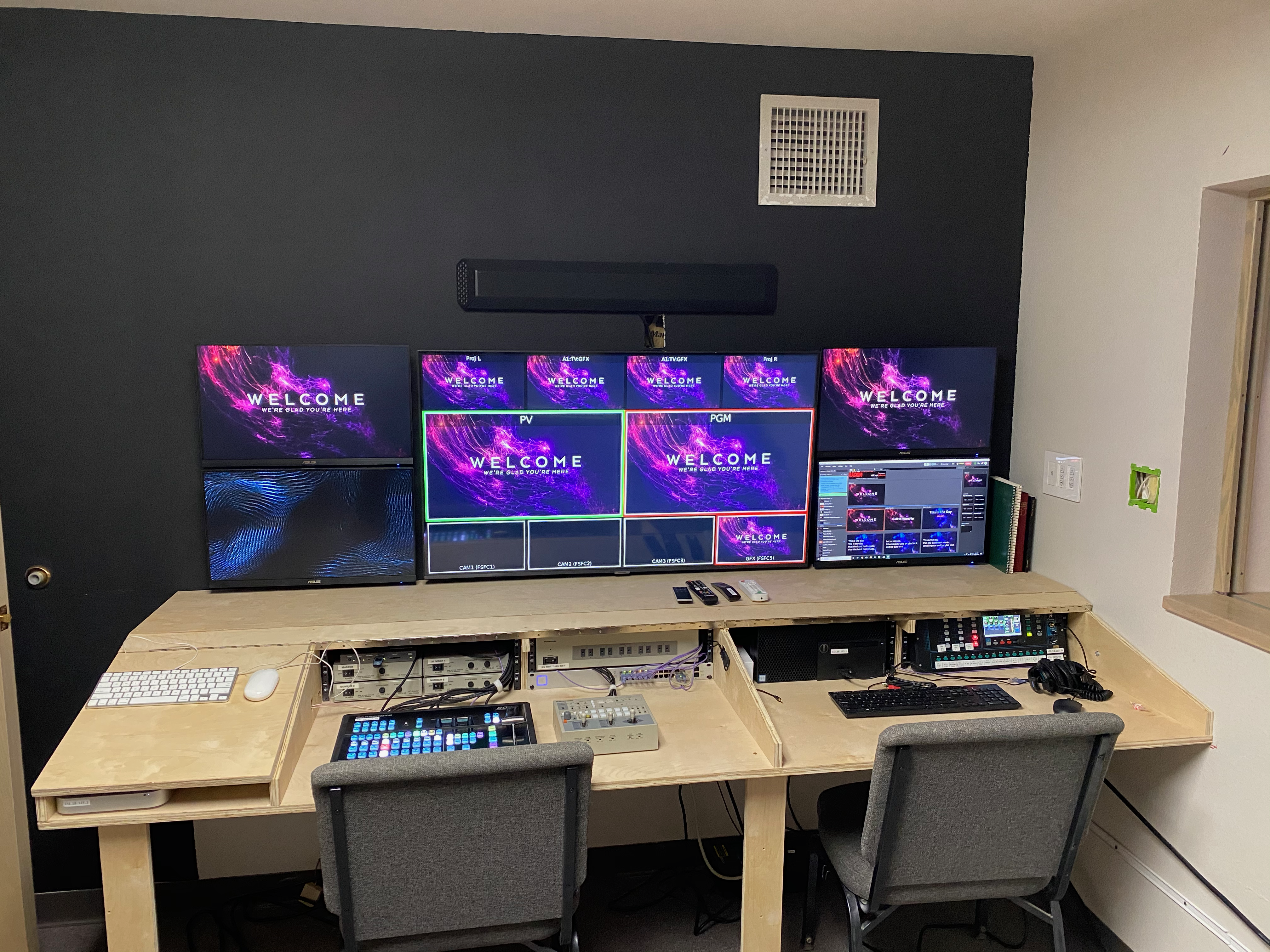
I’m going to veer off from my usual diet of wireless posts to bring you a howto post on the new video production desk that I built for the Family Life Center at our church.
Over the past year, we’ve been putting together a major upgrade to the video equipment in the FLC, because this is what we had…
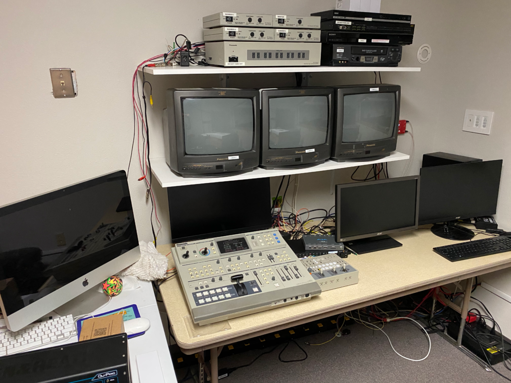
If you’re young, you may not recognize some of this. That switcher is a Panasonic AG-MX50, coupled with a 3-camera PTZ system of the same era. The AG-MX50 was introduced sometime around 1990, and quickly gained popularity not just for live production, but for anyone doing tape to tape edits – I first used this same system when working in the A/V department in college, and it was a pretty slick piece of kit then. Our FLC was built in 2002, and eventually inherited this video system from the sanctuary when it was upgraded several years back. To say that this system is past its prime would be a gross understatement.
The projectors in the room were also getting on in years, and in dire need of replacement. So we looked at what we needed to bring the video in our most attended venue into the 21st Century, and continuing a video ministry that has been in operation since the mid-1970s.
Background: We are a United Methodist church in a county seat town in central Kansas – about 250 a week in worship between two venues – while that’s big by United Methodist standards, we’re not one of these big high-tech churches – we do a lot with a little. (Long-time readers of the blog will remember that I worked at one of those big high-tech churches about a decade ago… It’s remarkable how much of those ideas can be scaled down to a “normal” sized church. The overall project budget for this video upgrade was under $40,000, and we included in that about 20-25% wiggle room for random cables, connectivity, and, apparently, building furniture. That little stuff adds up after a while.
The first piece was to add a couple of 75″ TVs (Samsung 7 series) in the front of the room on either side of the stage. This allowed people sitting in front to see what was on the screens, which were roughly even with the first row of seating. Our existing projectors were running 4:3 off a VGA signal that was being split and amplified and sent over some heavy duty cables to the projectors. The TVs didn’t support any kind of analog input, so I ran some Belden 9116 RG6 cable and put a Decimator MD-HX on the computer end, and a couple of BlackMagic HDMI converters at the TVs, and a WiiStar VGA converter on the projectors, as well as an SDI to analog converter for the switcher running the stream. Later, when we added the new projectors (Panasonic PT-VMZ60), I put a Decimator MD-LX to get the signal to HDMI. the Projectors and TVs were daisy-chained on the SDI link.
The next piece of the puzzle was to upgrade our switcher – We started with a BlackMagic ATEM TV Studio, and added a couple of WiiStar analog to SDI converters, but the ATEM TVS is rather finicky about input formats, which only one of the converters managed to output correctly. So we ran the SDI from the Decimator into the TVS, and then used an analog to SDI converter to get the output of the analog switcher into the TVS as well, and switched using both. This is also when we added an Aja Helo encoder to the mix, as my Teradek VidiU (a demo from the vendor) had decided to call it quits.
After several months of this, the funds were finally available to purchase the Ross Carbonite Solo switcher we had decided upon (cheaper than the ATEM 1ME unit, with more features, but most importantly, it had 6 build in scan converters, meaning I wouldn’t have to get a small platoon of Decimator MD-HX units just to make the ATEM happy. We opted for the 9-input unit rather than the 13, as this was plenty for our needs. We also purchased the AW-RP150 camera controller so we’d be ready when the funds came in for the new cameras – We had to replace a lot of infrastructure in order to be ready for the cameras.
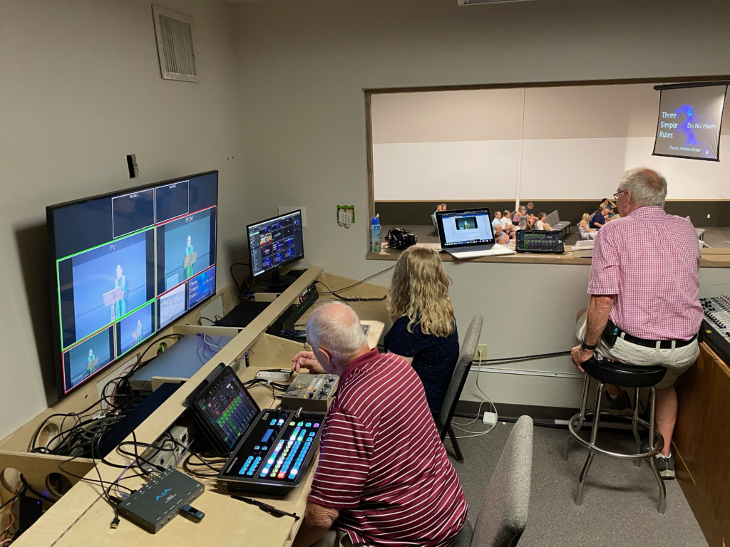
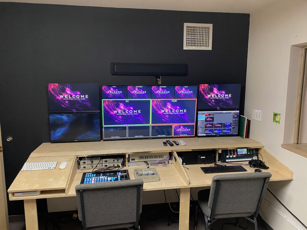
Naturally, this meant we were going to have to make a major update to our workspace – as you can see above, it was kind of cluttered and not very functional. So I set about making a custom desk that would accommodate all the gear, keeping cable messes out of sight, and making the overall system much more user-friendly.
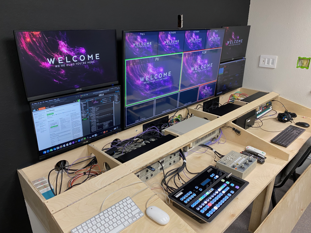
I then considered the overall layout and found that a 50″ TV as a central multiviewer with two 24″ monitors stacked on either side would give us an array of displays that would give us a good overview of the production. I had initially planned on mounting it about 8″ above the surface of the desk, but that ended up being a lot less ergonomic than we had figured, so I ended up moving them down almost flush with the flat surface of the desk, meaning I had to mount the sound bar above (suboptimal, but functional).
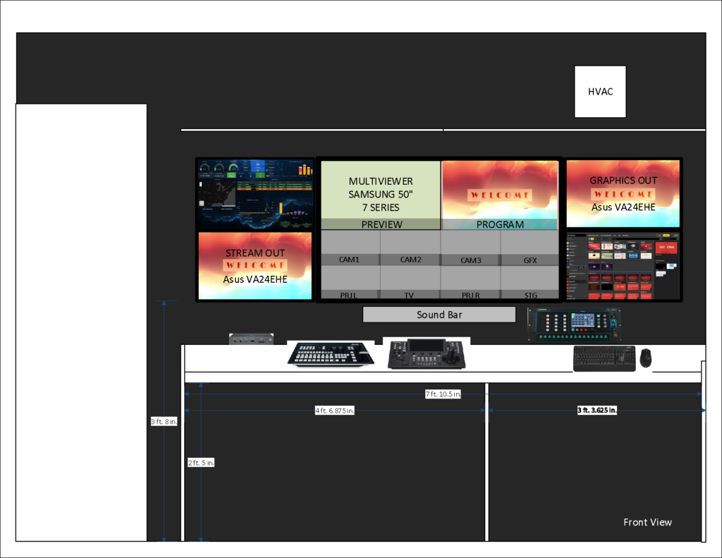
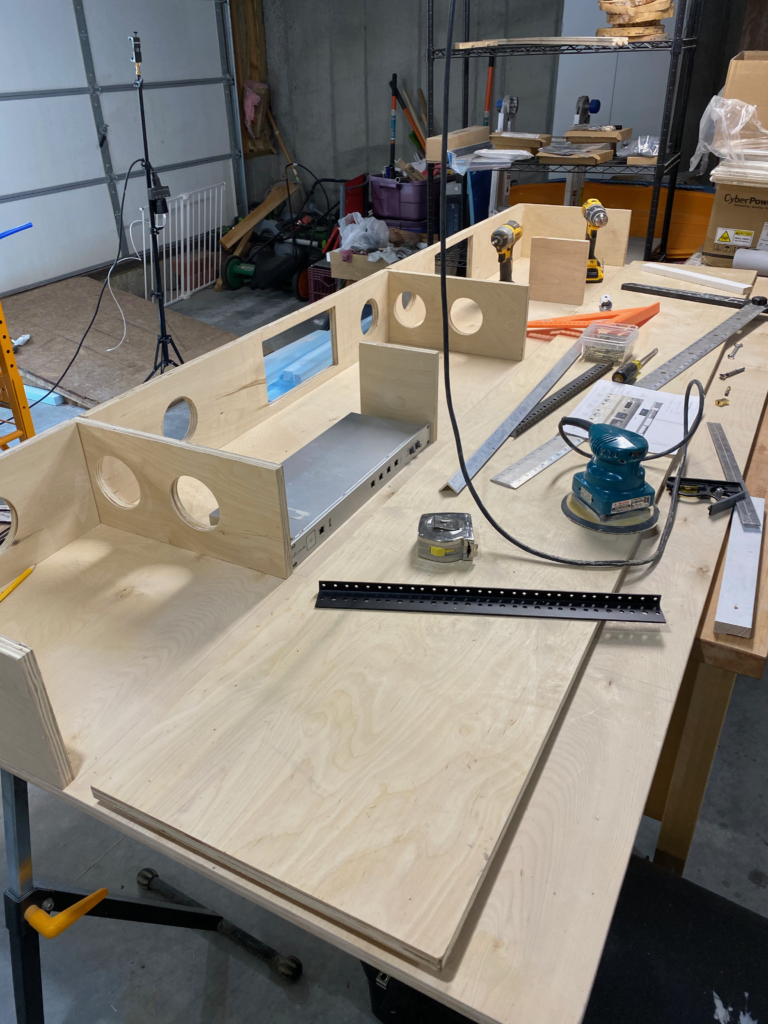
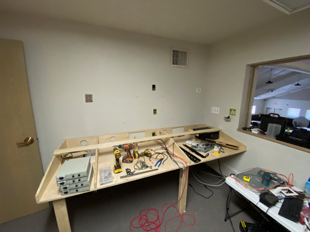
I had about 8 feet of space to work with, and could go about 3 feet deep. After tinkering around in Visio, I was able to come up with a design that could be cut from two sheets of cabinet grade plywood, provide a sloped front, in which the switcher and camera controller could be flush mounted, while also providing four bays with 4U of rack space each, where I could mount things like power strips, network switch, a patch panel, and various other bits.
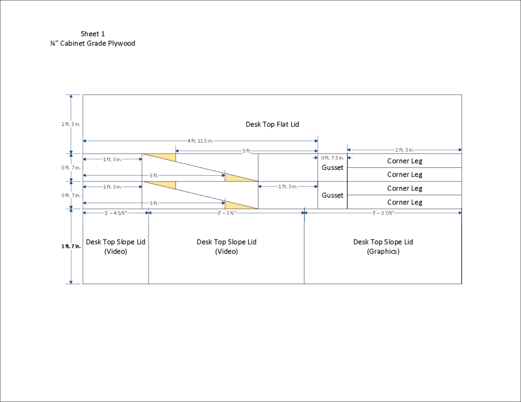
Note: the vertical dotted lines on the ribs are NOT CUTS! the lumber yard missed that memo, and I had to work around that.
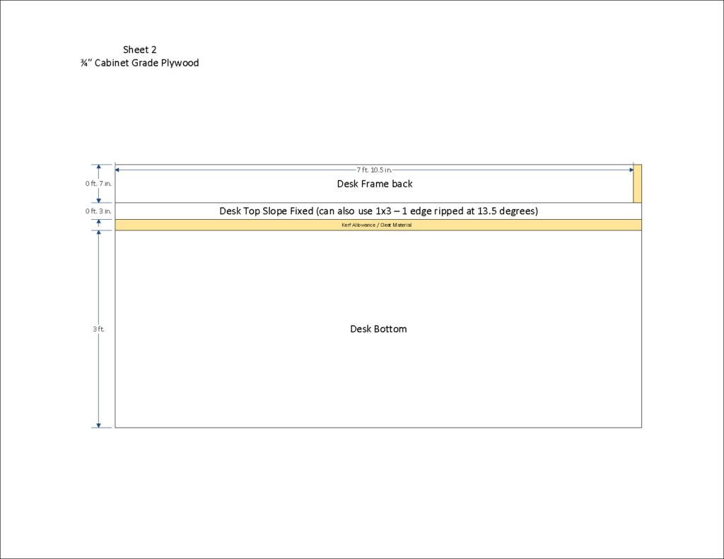
An artifact of this being a two-sheet design means that there’s bar at the top of the sloped face that is fixed in place – That does somewhat impede the access to the top rack space (more on that in a second) – you could use a third sheet and make the movable panels go the whole height.
This is also where I discovered that the “imported birch faced cabinet plywood” that my local lumber yard sells is basically 3/4″ worth of layers of cheap luaun with a birch veneer and a whole lot of glue. I would not recommend this material or use it again. It’s a pain in the ass to saw and sand, and it splinters like crazy. It got the job done, but it’s got some challenges (running a hole saw on this stuff sucks). Well worth spending an extra few bucks on actual hardwood cabinet plywood.
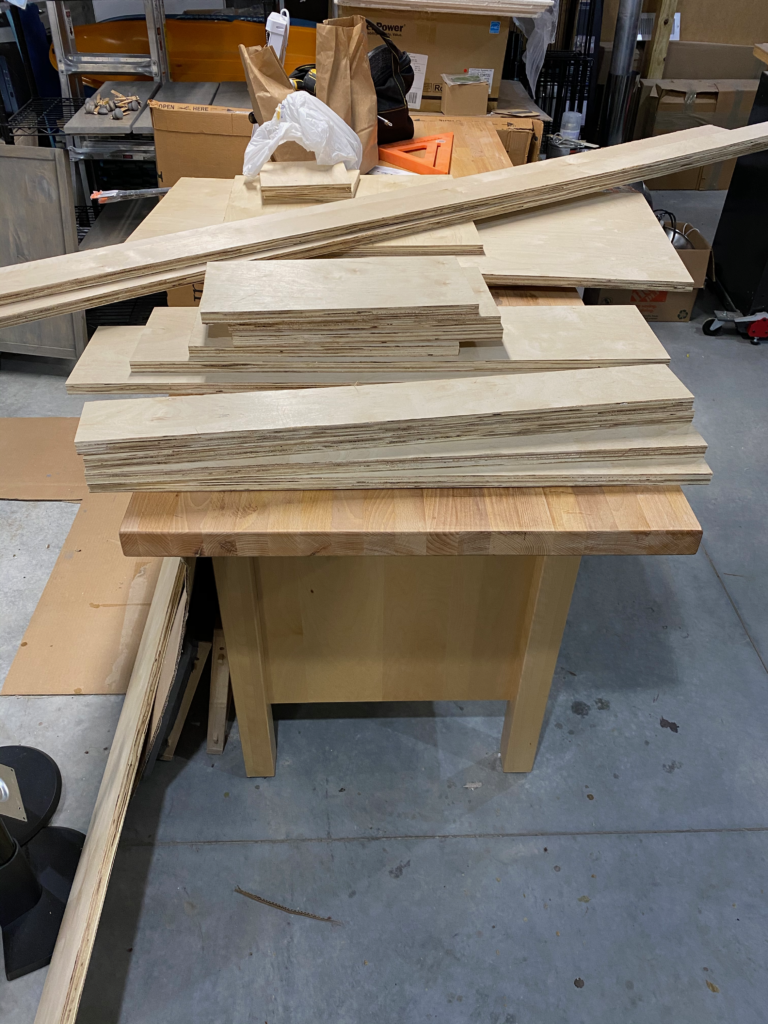
Once I got the big cuts done by the lumber yard, I had another member of the tech team handle the angle cuts with his table saw (where he also noticed that the wood quality was poor), since I lacked that particular bit of equipment.
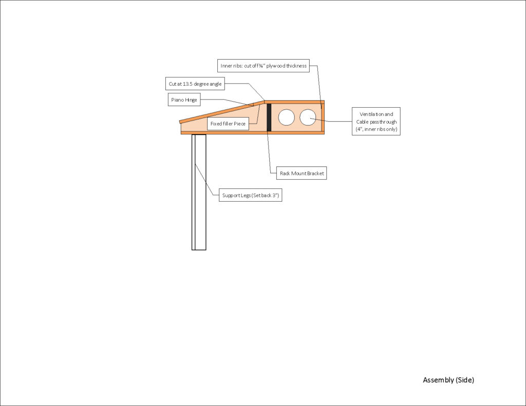
Getting down into the details of the assembly required some planning ahead. I had initially planned for 6″ space inside, until I realized that our current presentation computer is 6.2″ high. Then I remembered that 4U of rack space is 7″, so I altered the design (before cutting!) to create four bays of 4U each, and ordered four sets of rack mounting rails to go in the space.
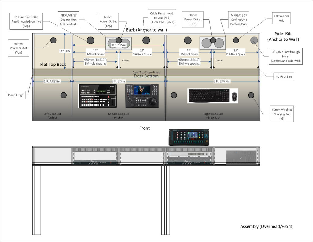
You’ll notice here that I have a bunch of passthru holes and outlet packs on the back deck – those have mostly gone away owing to the TVs and screens taking up the back 5″ or so of the deck. I may still add a few on the back deck between the rack bays. Once I get the hinged lids going, they will contain a wireless charging pad for mobile devices.
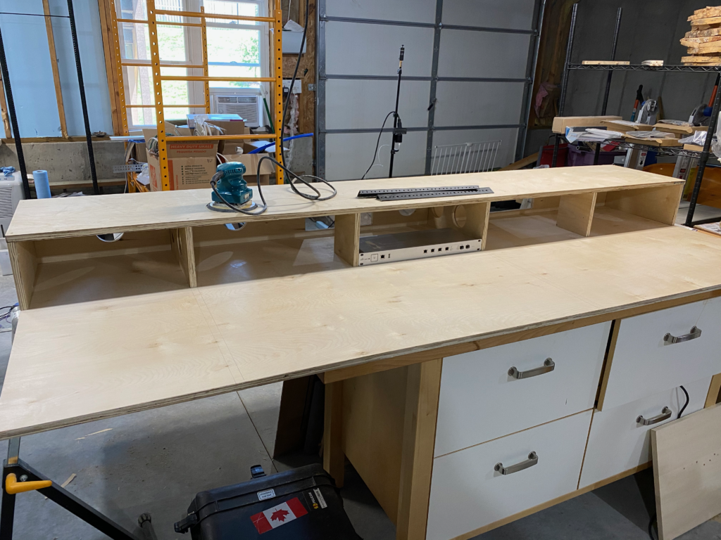
When it came time to haul it over to the church, I removed the top panels just to make it easier to maneuver and carry into the booth.
Installation time: A couple of scraps from cutting the ventilation holes were squared off on the radial arm saw and I used them as cleats to support the desk (using a laser to align it with the top of the legs)
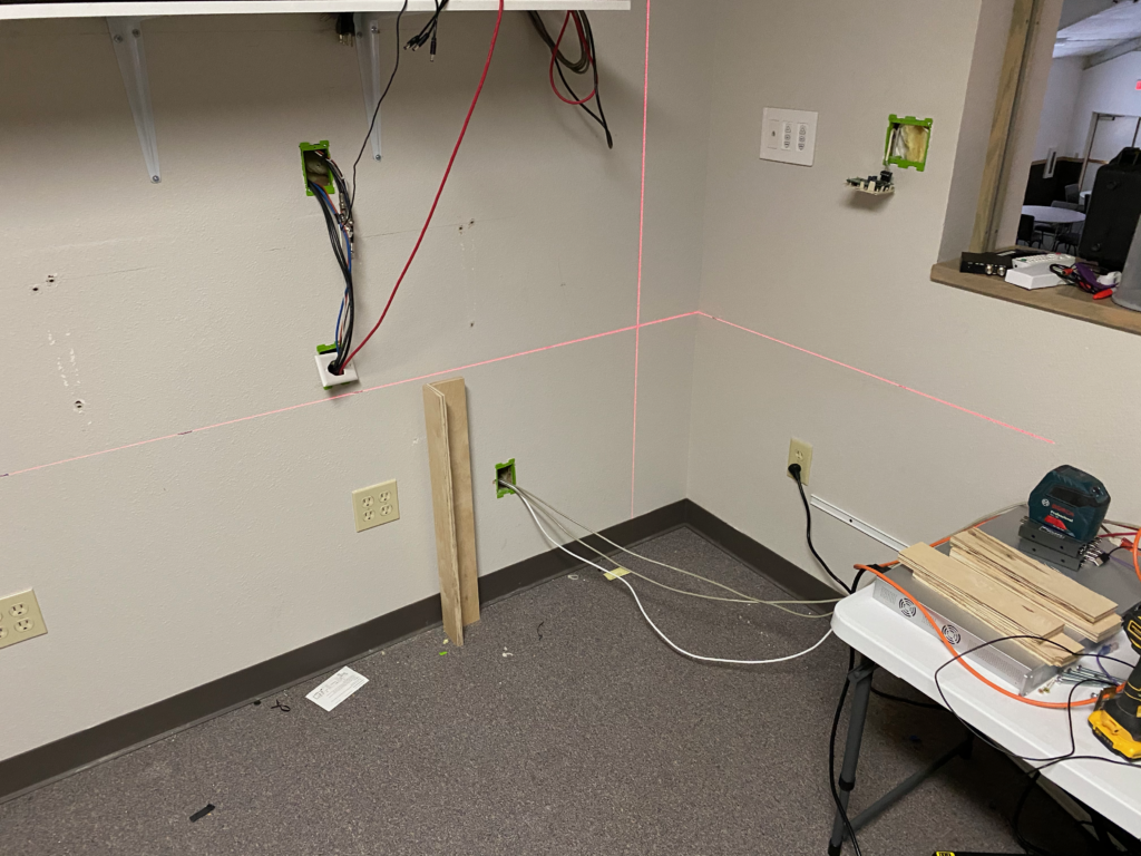
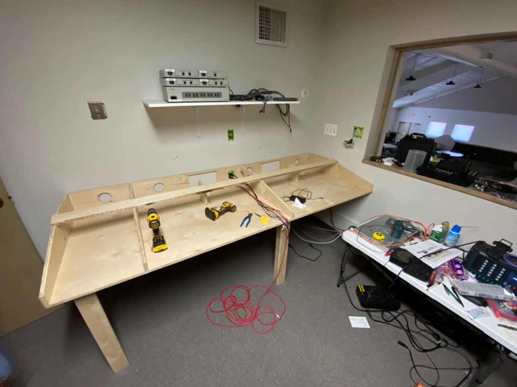
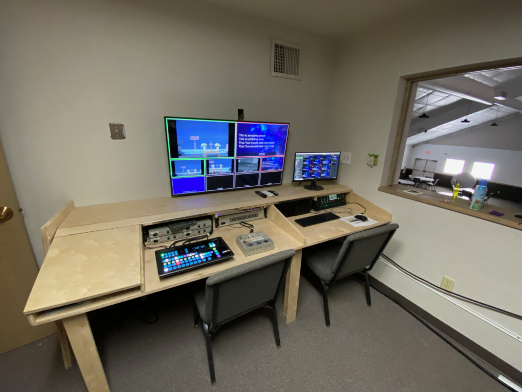
I left the front lip open to provide for airflow.
I was able to find a set of matching Asus monitors that were inexpensive and used a VESA mount, and while those were on their way, I painted the wall behind them in flat stage black (makes the displays blend in better, and the wall was in dire need of a coat of paint anyway, so I used some of the paint left over from painting the stage)
Materials List:
- 2 or 3 sheets of 3/4″ cabinet grade hardwood plywood
- 2″ finish screws (recommend Torx or Robertson head)
- 4 sets of 4U rack brackets
- 2 36″ piano hinges
- 1 24″ piano hinge (you’ll need to cut this one to length)
- Any trim or edge veneer you wish – We’re putting a lip on the bottom edge of the lid.
- 2 AC Infinity AirPlate fan packs – Based on the way I built our desk, I had to flip the fans around to change the flow direction. You can either vent below the cabinet into the existing space, or vent to the rear (in our facility, the wall leads to a big empty ceiling space above the kitchen. These have a manual speed control, but a thermostat control version is also available.
Optional Components:
- Wireless Charging Pads
- Power Ports
- USB Ports
- DIN Rail and DC Power Supplies (5V/12V/24V)
- DC Terminal Blocks
- DC Power Tails (or terminals)
Tools:
- Hole saws for the large holes
- Forstner bits for smaller holes
- Drill (and small bits for pilot holes)
- Kreg Jig for pocket screws
- Belt Sander with coarse belt (for evening things out)
- Laser level (for installation)
- Orbital sander with 120/180/220 grit pads (for smoothing things out)
- Power driver (impact or drill – cordless helps a LOT here)
- T square/Try square
- Clamps
- Table Saw
- Radial Arm or sliding miter saw
- Jig saw or reciprocating saw
Tech Equipment:
- Multiviewer Display: Samsung 7 Series 50″ TV (although an excellent alternative would be the Samsung DC49J signage display, which ditches all the SmartTV nonsense.
- Side Displays: Asus VA24EHE
- Mounting for the TV/Monitors can be just about anything that works for you.
- Rack Mount PDU (options for this are numerous!)
- Audio Mixer: Allen & Heath Qu-PAC
- Video Switcher: Ross Carbonite Solo (sourced from Force Technology Solutions)
- Camera Controller: Panasonic AW-RP150 (also from Force)
- Projectors: Panasonic PT-VMZ60
- Stream Encoder: Aja Helo
- Analog Camera Converters: WiiStar
- SDI Cables: RG179 slim cables
- Installed SDI Cables: Belden 9116 with compression BNC
- SDI to HDMI: Decimator Design MD-LX
- Automation Computer: Mac Mini with Dante Virtual Sound Card, BitFocus Companion, InfluxDB, Grafana
- Elgato StreamDeck
- Network Switch: UniFi 24-port 250W PoE (although I would recommend the Aruba InstantON series)
And that’s the story so far… I’ll update the post as changes warrant.
